
Manual

Rockwell Automation Publication 1512A-UM100F-EN-P - May 2013 57
Maintenance Chapter 5
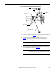
8. Actuate the Isolation Switch handle to verify the travel angle.
If the angle is incorrect, repeat steps 5 through 7 until desired travel angle is
reached.
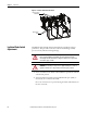
Isolation Switch Mechanism
Grounding Adjustment
1. Complete the Power Lockout Procedure (refer to Power Lock-out
Procedure on page 41).
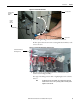
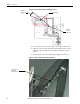
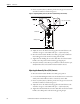
2. Inspect the grounding of the isolation switch blades. When the isolation
switch handle is in the OFF position, the isolation switch blades must fully
engage the grounding pins and be within 1.5 mm (0.06 in.) of the ground
bar (see Figure 58
). When the isolation switch handle is in the ON
position, the blades must fully engage the incoming line stabs.
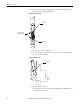
Figure 58 - Isolation Switch Grounding Adjustment
ATTENTION: All three isolation switch linkage assemblies must meet the angle
tolerance requirements.
ATTENTION: To avoid shock hazards, lock out incoming power (refer to Power
Lock-out Procedure on page 41) before working on the equipment. Verify with a
hot stick or other appropriate voltage measuring device that all circuits are
voltage free. Failure to do so may result in severe burns, injury or death.
Ground Bar
Maximum Gap 0.06 in. (1.5 mm) between ground
Bar and Isolation Switch in open position
Isolation Switch Blade
Incoming Line Stab
Auxiliary Contact