
Manual

50 Rockwell Automation Publication 1512A-UM100F-EN-P - May 2013
Chapter 5 Maintenance
1. Complete the Power Lockout Procedure (refer to Power Lock-out
Procedure on page 41).
2. Open the medium voltage door. Use the Door Interlock Circumvention
procedure (refer to Door Interlock Circumvention
on page 40) to move
the isolation switch handle halfway between the OFF and ON position
(see Figure 49
). Keep the handle in this position until the adjustment
procedure is completed.
3. With the contactor in the OFF position, insert a 1.5 mm (0.060 in.) feeler
gauge in the gap between the interlock lever and the isolation switch
operating lever. The gap must be between 1.0 mm to 2.0 mm (0.039 in. to
0.078 in.).
4. To reduce the gap distance, follow steps 5-7.
To increase the gap distance, follow steps 8-10.
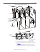
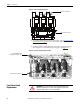
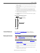
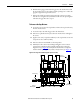
Figure 49 - Isolation Switch Handle Adjustments
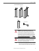
To Reduce the Gap Distance
5. Loosen the two screws in the stop bracket and move the stop bracket up
against the interlock lever.
Isolation Switch
Operating Lever
Isolation Switch
Handle at halfway
position
Nyloc Nut
Contactor Interlock Lever
Contactor Interlock Rod
Stop Bracket
Switch Interlock Lever
Gap: 0.045...0.060 in.
(1.1...1.5 mm)