
Manual

44 Rockwell Automation Publication 1512A-UM100F-EN-P - May 2013
Chapter 5 Maintenance
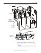
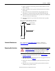
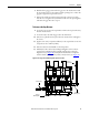
Figure 43 - Contactor Voltage Checkpoints
7. Use the Door Interlock Circumvention procedure (refer to Door Interlock
Circumvention on page 40) to move the isolation switch handle to the
ON position.
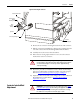
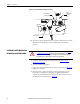
8. Check the isolation switch blades with a hot stick or appropriate voltage
measuring device to verify that they are voltage free (see Figure 44
).
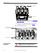
Figure 44 - Isolation Switch Voltage Check Points
9. Once all power circuits are verified to be voltage free, move the isolation
switch handle back to the OFF position. The unit is now safe to service.
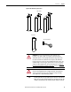
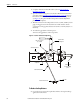
Fuse Removal and
Replacement
Check line-side power here
Check load-side power here
Isolation Switch Blades must
fully engage Incoming Line Stabs
Check incoming line voltage here
ATTENTION: Only personnel who have been trained and understand the
Bulletin 1500 product line are to work on this equipment. Suitable safety
equipment and procedures are to be used at all times.