
Manual

Rockwell Automation Publication 1512A-UM100F-EN-P - May 2013 31
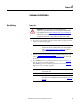
Common Installation Chapter 4
Ground Bus
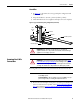
1. See Figure 36 to determine the correct ground splice configuration and
assemble as shown.
2. Torque the hardware to 15 N•m ± 1 N•m (12 lb•ft ± 1 lb•ft).
3. Check all hardware for correct tightness and replace all covers and plates.
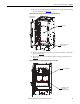
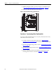
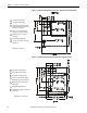
Figure 36 - Typical Ground Bus Splicing Configuration (Front View)
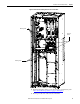
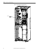
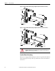
Incoming Line Cable
Connections
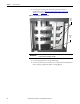
Incoming cables are connected to the power bus in the last section on the left.
1. Remove the center-back plate or side plate to access the power bus. If access
to the rear of the unit is not possible, refer to Access to the Power Bus
on
page 7 for Standard or Access to the Power Bus on page 20 of Chapter 3
for ArcShield enclosures.
Ground Bus Support
Main
Ground
Bus
Hex Nut
Lock Washer
Flat Washer
Ground Bus Splice Bar
ATTENTION: Ensure all barriers are replaced before re-energizing the
equipment. Failure to do so may result in electrical faults and cause damage to
equipment or severe injury to personnel.
ATTENTION: To avoid shock hazards, lock out incoming power (refer to Power
Lock-out Procedure on page 41 of Chapter 5) before working on the equipment.
Verify with a hot stick or appropriate voltage measuring device that all circuits
are voltage free. Failure to do so may result in severe burns, injury or death.
IMPORTANT
For Non-ArcShield units, cable size should not exceed 1-750 MCM or
2-500 MCM per phase.
For ArcShield units, cable size should not exceed 1-500 MCM or 2-4/0 per
phase. For larger cables, an incoming line module must be used.