
Manual

24 Rockwell Automation Publication 1512A-UM100F-EN-P - May 2013
Chapter 3 Installation – Arc-Resistant (ArcShield)
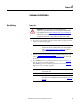
7. Install incoming line cables to power bus. Torque to specifications (refer
to Recommended Torque Values
on page 2 of Chapter 1) (Figure 29).
8. Reverse procedure after cables have been installed.
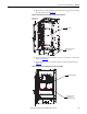
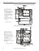
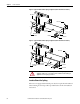
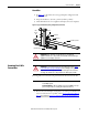
Figure 29 - Power Bus with Bottom Access Barrier Removed
Front Access – Top Incoming Cables (Top Entry/Exit)
Top entry one high ArcShield units are 0.9 m (36 in.) wide versus bottom entry
units which are 0.7 m (26 in.) wide.
1. Complete the Power Lock-out Procedure (refer to Power Lock-out
Procedure on page 41 of Chapter 5) for both the medium voltage and the
power bus.
2. Open the top medium voltage cell door (refer to Opening the Low Voltage
Doors on page 15).
3. Open the bottom empty cell door (refer to Opening the Medium Voltage
Door on page 16).
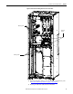
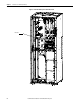
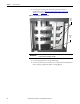
4. Remove retaining screws from removable bus access barriers to expose
incoming cable connection to main bus (Figure 30
and Figure 31).