
Manual


20 Rockwell Automation Publication 1512A-UM100F-EN-P - May 2013
Chapter 3 Installation – Arc-Resistant (ArcShield)
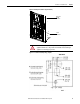
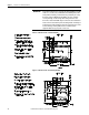
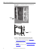
Figure 22 - Joining Sections
Access to the Power Bus
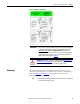
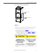
Rear Access
1. Remove the hardware securing the center rear bus access cover (Figure 23).
2. Remove the center rear bus access cover.
3. Once the center rear bus cover is removed you will see the three bus bars
(Figure 25
).
Power Bus
cutout holes
must align
Silicone is applied around
power bus cutout area to
prevent gas leakage
between joined cabinets
ATTENTION: This procedure requires contact with medium voltage
components. To avoid shock hazards, lock out incoming power before working
on the equipment (refer to Power Lock-out Procedure
on page 41 of Chapter 5).
Verify with a hot stick or appropriate voltage measuring device that all circuits
are voltage free. Failure to do so may result in severe burns, injury or death.
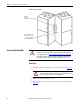
ATTENTION: The rear cover plates are made from 12 gauge metal and
are mounted in board of the main structure. The covers will drop inside
if care is not taken as you remove the mounting bolts.