
Manual

Rockwell Automation Publication 1512A-UM100F-EN-P - May 2013 11
Installation – Standard Enclosure Chapter 2
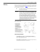
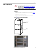
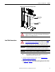
Figure 12 - Access to Bottom Incoming Line Cables
Load Cable Connections
1. Complete the Power Lockout procedure (refer to Power Lock-out
Procedure on page 41 of Chapter 5).
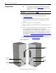
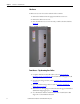
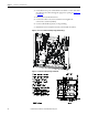
2. Remove the appropriate cable conduit opening plate(s) from the cabinet
(see Figure 13
to Figure 15). The plate may be punched or cut to mount
conduit.
ATTENTION: Ensure all barriers are replaced before re-energizing the
equipment. Failure to do so may result in electrical faults and cause damage to
equipment or severe injury to personnel.
Cable duct
access barrier
Bottom incoming
cable duct located
in power cell
ATTENTION: To avoid shock hazards, lock out incoming power (refer to Power
Lock-out Procedure on page 41 of Chapter 5) before working on the equipment.
Verify with a hot stick or appropriate voltage measuring device that all circuits
are voltage free. Failure to do so may result in severe burns, injury or death.
IMPORTANT
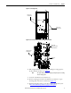
The current transformers may be positioned for top or bottom cable exit.
Follow the appropriate procedure described for your starter configuration.
IMPORTANT
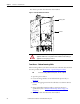
Cable size should not exceed 1-750 MCM or 2-500 MCM per phase.
TIP
Refer to Dimensional Drawings provided with order documentation for
additional details related to cabinet floor plan.