
Manual

Rockwell Automation Publication 1512A-UM100F-EN-P - May 2013 9
Installation – Standard Enclosure Chapter 2
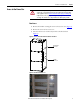
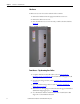
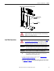
Figure 9 - Low Voltage Panel
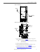
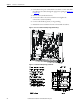
Figure 10 - Access to Power Bus with Low Voltage Panel Rotated
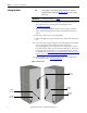
6. Pull on right-hand side of low voltage panel. Swing low voltage panel to
the front and left of cabinet (see Figure 10
).
7. Locate the removable bus access barriers (2).
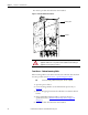
8. Remove retaining screws from removable bus access barriers to expose
incoming cable connections to main bus (see Figure 11
).
9. Install incoming line cables to power bus, torque to specifications (refer
to Recommended Torque Values
on page 2 of Chapter 1).
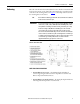
TIP
The power cell door must be in a fully opened position prior to rotating
the low voltage panel.
Remove self-
tapping screws
Remove 1/4
turn fasteners
Swing Open Low
Voltage Panel
Remove self-
tapping screws from
Bus Access Barriers
Bus Access
Barriers