
Manual

8 Rockwell Automation Publication 1512A-UM100F-EN-P - May 2013
Chapter 2 Installation – Standard Enclosure
Side Access
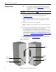
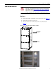
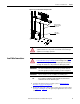
A side bus access cover is located on each side of the controller.
1. Remove the hardware from the appropriate side bus access cover.
2. Remove the side bus access cover.
3. Once the side bus access cover is removed, you will see the three bus bars.
(Figure 8
).
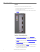
Figure 8 - Side Bus Access Cover Removed
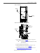
Front Access – Top Incoming Line Cables
1. Complete the Power Lockout Procedure (refer to Power Lock-out
Procedure on page 41 of Chapter 5) for both medium voltage power cells
and the power bus.
2. Open the low voltage cell door (refer to Opening the Low Voltage Doors
on page 3).
3. Open the medium voltage cell doors (refer to Opening the Medium
Voltag e Doors on page 4).
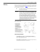
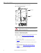
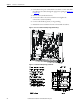
4. Remove the two self-tapping screws from the low voltage panel if installed.
(Installed for shipping purposes – see Figure 9
).
5. Use a flat head screwdriver and turn both of the 1/4-turn fasteners 180
degrees in a counterclockwise direction.