
Manual

6 Rockwell Automation Publication 1512A-UM100F-EN-P - May 2013
Chapter 2 Installation – Standard Enclosure
Joining Sections
6. Position the left side section on a level surface and secure the section in
place with 12 mm (1/2 in. [M12]) floor mounting bolts (refer
to Anchoring
on page 5).
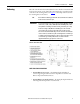
7. When joining NEMA/EEMAC Type 12 sections, apply a continuous
3 mm (1/8 in.) wide bead of silicon sealer around the perimeter of one
section.
8. Remove the side bus access covers if applicable.
9. Position the right section against the left section. Ensure that the surface is
level.
10. Secure the sections together using the 1/4-20 self-tapping screws. Thread
the screw through the 7 mm (0.281 in.) clearance hole to the
corresponding 6 mm (0.219 in.) pilot hole. To access the front clearance
holes of the left-side cabinet, open the medium voltage doors. To access the
rear clearance holes remove the rear covers of the starter. If rear access is
not available, refer to Front Access – Top Incoming Line Cables
on page 8
or Front Access – Bottom Incoming Cables
on page 10.
11. Secure the right section to the floor using 12 mm (1/2 in. [M12]) floor
mounting bolts (refer to Anchoring
on page 5).
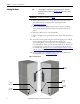
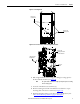
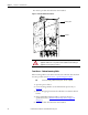
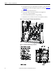
Figure 5 - Joining Sections
TIP
Joining hardware can be found in a package mounted to the front of the
shipping skid. Refer to publication MV-QS050_-EN-P
for level floor surface
requirements.
IMPORTANT
For Arc Resistant cabinets, see page 15.
F
r
o
n
t
F
r
o
n
t
Side Bus
Access Cover
0.219 Pilot
Holes (5x)
0.281 Pilot
Holes (5x)
0.281 Pilot
Holes (5x)
0.219 Pilot
Holes (3x)