User Manual Medium Voltage Controllers, 400A One-High Cabinet, Standard and Arc-Resistant Enclosure Publication 1512A-UM100F-EN-P
Important User Information Solid-state equipment has operational characteristics differing from those of electromechanical equipment. Safety Guidelines for the Application, Installation and Maintenance of Solid State Controls (publication SGI-1.1 available from your local Rockwell Automation sales office or online at http://www.rockwellautomation.com/literature/) describes some important differences between solid-state equipment and hard-wired electromechanical devices.
Summary of Changes This manual contains new and updated information. New and Updated Information This table contains the changes made to this revision.
Summary of Changes Notes: iv Rockwell Automation Publication 1512A-UM100F-EN-P - May 2013
Table of Contents Chapter 1 General Information Document Scope. . . . . . . . . . . . . . . . . . . . . . . . . . . . . . . . . . . . . . . . . . . . . . . . . . . 1 Starter Identification . . . . . . . . . . . . . . . . . . . . . . . . . . . . . . . . . . . . . . . . . . . . . . . 1 Recommended Torque Values . . . . . . . . . . . . . . . . . . . . . . . . . . . . . . . . . . . . . . 2 Chapter 2 Installation – Standard Enclosure Door Opening Procedure . . . . . . . . . . . . . . . . . . . . . . . . . . .
Table of Contents Chapter 5 Maintenance Tool Requirements . . . . . . . . . . . . . . . . . . . . . . . . . . . . . . . . . . . . . . . . . . . . . . . Recommended Torque Values . . . . . . . . . . . . . . . . . . . . . . . . . . . . . . . . . . . . . Door Interlock Circumvention . . . . . . . . . . . . . . . . . . . . . . . . . . . . . . . . . . . . Power Lock-out Procedure . . . . . . . . . . . . . . . . . . . . . . . . . . . . . . . . . . . . . . . . Fuse Removal and Replacement . . . . . . . . . . . .
Table of Contents Cabinet Preparation . . . . . . . . . . . . . . . . . . . . . . . . . . . . . . . . . . . . . . . . . . Plenum Placement on Structure . . . . . . . . . . . . . . . . . . . . . . . . . . . . . . . STEP 2 – Alignment of “Side-by-Side” Plenums . . . . . . . . . . . . . . . . . . . . STEP 3 – Sequence of Final Assembly . . . . . . . . . . . . . . . . . . . . . . . . . . . . . STEP 4 – Closing the Front of the Plenum Sections . . . . . . . . . . . . . . . .
Table of Contents Notes: 4 Rockwell Automation Publication 1512A-UM100F-EN-P - May 2013
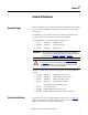
Chapter 1 General Information Document Scope This User Manual pertains to the Rockwell Automation Bulletin 1512A medium voltage controller. The Bulletin 1512A structure provides one complete MV controller unit. The installation section provides instructions for both the standard enclosure type and the Rockwell Automation arc resistant type (ArcShield).
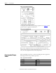
Chapter 1 General Information Figure 1 - Typical Structure Nameplate A nameplate is also found in the low voltage compartment (see Figure 2) with specific unit motor application information. Figure 2 - Typical Unit Nameplate Refer to these nameplates whenever you contact Rockwell Automation for assistance. Be prepared to provide such information as series number, structure series, unit series, diagram schematic and catalog number.
Chapter 2 Installation – Standard Enclosure For information on the installation site preparation, see Publication MV-QS050_-EN-P. IMPORTANT ATTENTION: Use suitable personal protective equipment (PPE) per local codes or regulations. Failure to do so may result in severe burns, injury or death. Door Opening Procedure Opening the Low Voltage Doors Low voltage doors are identified as LV in Figure 3. 1.
Chapter 2 Installation – Standard Enclosure ATTENTION: Medium voltage components may be located behind the swingout low voltage panel (standard cabinets only). Complete the power lockout procedure (refer to Power Lock-out Procedure on page 41 of Chapter 5) before attempting to open the swing-out low voltage panel. Failure to do so may result in severe burns, injury or death.
Installation – Standard Enclosure Anchoring Chapter 2 Place the controller in the desired installation location. The floor must be flat and level. Use four 12 mm (1/2 in. [M12]) floor mounting bolts to securely fasten the controller to the mounting surface. See Figure 4 as an example of the location of the mounting holes in the cabinet. TIP Refer to Dimension Drawing provided with order documentation for additional details related to cabinet floor plan.
Chapter 2 Installation – Standard Enclosure Joining Sections TIP IMPORTANT Joining hardware can be found in a package mounted to the front of the shipping skid. Refer to publication MV-QS050_-EN-P for level floor surface requirements. For Arc Resistant cabinets, see page 15. 6. Position the left side section on a level surface and secure the section in place with 12 mm (1/2 in. [M12]) floor mounting bolts (refer to Anchoring on page 5). 7.
Installation – Standard Enclosure Access to the Power Bus Chapter 2 ATTENTION: This procedure requires contact with medium voltage components. To avoid shock hazards, lock out incoming power before working on the equipment (refer to Power Lock-out Procedure on page 41 of Chapter 5). Verify with a hot stick or appropriate voltage measuring device that all circuits are voltage free. Failure to do so may result in severe burns, injury or death. Rear Access 1.
Chapter 2 Installation – Standard Enclosure Side Access A side bus access cover is located on each side of the controller. 1. Remove the hardware from the appropriate side bus access cover. 2. Remove the side bus access cover. 3. Once the side bus access cover is removed, you will see the three bus bars. (Figure 8). Figure 8 - Side Bus Access Cover Removed Front Access – Top Incoming Line Cables 1.
Installation – Standard Enclosure Chapter 2 Figure 9 - Low Voltage Panel Remove 1/4 turn fasteners Remove selftapping screws Figure 10 - Access to Power Bus with Low Voltage Panel Rotated Remove selftapping screws from Bus Access Barriers Swing Open Low Voltage Panel Bus Access Barriers 6. Pull on right-hand side of low voltage panel. Swing low voltage panel to the front and left of cabinet (see Figure 10).
Chapter 2 Installation – Standard Enclosure 10. Reverse procedure after cables have been installed. Figure 11 - Power Bus with Barrier Removed Low Voltage Panel Power Bus ATTENTION: Ensure all barriers are replaced before re-energizing the equipment. Failure to do so may result in electrical faults and cause damage to equipment or severe injury to personnel.
Installation – Standard Enclosure Chapter 2 Figure 12 - Access to Bottom Incoming Line Cables Bottom incoming cable duct located in power cell Cable duct access barrier ATTENTION: Ensure all barriers are replaced before re-energizing the equipment. Failure to do so may result in electrical faults and cause damage to equipment or severe injury to personnel.
Chapter 2 Installation – Standard Enclosure 3. Load cables for the power cell should be routed before control cables. Pull the cables into the cabinet through the appropriate opening (see Figure 13 to Figure 15). 4. Remove current transformer barriers. 5. Connect the cables to the current transformers and tighten the connections to 65 N•m (48 lb•ft). 6. Connect cable shields (if present) to the ground lug. 7. Reinstall the current transformer barrier and reassemble the cabinet.
Installation – Standard Enclosure Chapter 2 Figure 15 - Routing of Load Cables (Top exit shown) Route Cables through Access Hole Current Transformer ATTENTION: Ensure all barriers are replaced before re-energizing the equipment. Failure to do so may result in electrical faults and cause damage to equipment or serious injury to personnel.
Chapter 2 Installation – Standard Enclosure Notes: 14 Rockwell Automation Publication 1512A-UM100F-EN-P - May 2013
Chapter 3 Installation – Arc-Resistant (ArcShield) This installation section contains information related only to the Rockwell Automation arc resistant enclosures, referred to now as “ArcShield”. IMPORTANT For information on the installation site preparation, see Publication MV-QS050_-EN-P. ATTENTION: Use suitable personal protective equipment (PPE) per local codes or regulations. Failure to do so may result in severe burns, injury or death.
Chapter 3 Installation – Arc-Resistant (ArcShield) ATTENTION: Complete the Power Lockout procedure (refer to Power Lock-out Procedure on page 41 of Chapter 5) before beginning any service procedures to the unit. Failure to do so may result in severe burns, injury or death. Opening the Medium Voltage Door Figure 18 - Access to Medium Voltage Compartments IMPORTANT The medium voltage door has its own isolation switch handle and interlocking safeguards.
Installation – Arc-Resistant (ArcShield) Chapter 3 Figure 19 - Label on Arc Resistant Door IMPORTANT The last step in closing the medium voltage door, ensure all door locking bolts on the right side of the MV door are in place and tightened until the door is flush with the flange. Do not overtighten the bolts. If the door is not securely fastened, it will not be possible to move the isolation switch handle to the ON position.
Chapter 3 Installation – Arc-Resistant (ArcShield) IMPORTANT Pre-determined cabinets have been designed for Uniform Building Code (UBC) seismic zone 1, 2A, 2B, 3 and 4, and IBC (International Building Code) seismic activity without overturning or lateral movement, provided they are securely mounted according to UBC, IBC and local building codes. This can include concrete pad design, steel floor design and the sizing of cabinet anchors.
Installation – Arc-Resistant (ArcShield) Chapter 3 NOTES FOR SEISMIC APPLICATIONS • For installations on concrete – the minimum depth and radius of concrete supporting the cabinet anchors is dependent on seismic loads. Refer to important information above. • For installations on a metal structure – the metal plate depth and cabinet anchoring method is dependent on seismic loads. Joining Sections Joining hardware can be found in a package mounted to the front of the shipping skid.
Chapter 3 Installation – Arc-Resistant (ArcShield) Figure 22 - Joining Sections Power Bus cutout holes must align Silicone is applied around power bus cutout area to prevent gas leakage between joined cabinets Access to the Power Bus ATTENTION: This procedure requires contact with medium voltage components. To avoid shock hazards, lock out incoming power before working on the equipment (refer to Power Lock-out Procedure on page 41 of Chapter 5).
Installation – Arc-Resistant (ArcShield) Chapter 3 Figure 23 - Access to Power Bus from Side and Rear of Cabinet Side Bus Access Cover Center Rear Bus Access Cover Side Access A side bus access cover is located on each side of the controller, when required. 1. Remove the hardware from the appropriate side bus access cover. 2. Remove the side bus access cover (Figure 23). 3.
Chapter 3 Installation – Arc-Resistant (ArcShield) Figure 25 - Side Bus Access Cover Ground Connection (Rear Access Cover removed to show connection point) Side Bus Access Cover Ground Connection Figure 26 - ArcShield Ground Plate Removable Handle Front Access – Bottom Incoming Cables (Bottom Entry/Exit) 1. Complete the Power Lock-out Procedure (refer to Power Lock-out Procedure on page 41 of Chapter 5) for both the medium voltage power cell and the power bus. 2.
Installation – Arc-Resistant (ArcShield) Chapter 3 4. Remove the two self-tapping screws from the low voltage panel, and swing open the LV panel (see Figure 27). Figure 27 - Removal of Access Door with Low Voltage Panel Rotated Swing Open Low Voltage Panel Access Door Remove bolts securing this access door 5. Remove the 24 bolts that secure the access door to the frame – remove the panel (see Figure 27). 6. Remove the two screens at the back of the low voltage compartment (see Figure 28).
Chapter 3 Installation – Arc-Resistant (ArcShield) 7. Install incoming line cables to power bus. Torque to specifications (refer to Recommended Torque Values on page 2 of Chapter 1) (Figure 29). 8. Reverse procedure after cables have been installed. Figure 29 - Power Bus with Bottom Access Barrier Removed Front Access – Top Incoming Cables (Top Entry/Exit) Top entry one high ArcShield units are 0.9 m (36 in.) wide versus bottom entry units which are 0.7 m (26 in.) wide. 1.
Installation – Arc-Resistant (ArcShield) Chapter 3 Figure 30 - Removal of Low Voltage Barriers to Access Power Bus Retaining Screws Bus Access Barriers Retaining Screws 5. Install incoming line cables to power bus. Torque to specifications (refer to Recommended Torque Values on page 2 of Chapter 1). 6. Reverse procedure after cables have been installed.
Chapter 3 Installation – Arc-Resistant (ArcShield) Figure 31 - Power Bus with Top Access Barrier Removed Power Bus 26 Rockwell Automation Publication 1512A-UM100F-EN-P - May 2013
Installation – Arc-Resistant (ArcShield) Load Cable Connections Chapter 3 ATTENTION: To avoid shock hazards, lock out incoming power (refer to Power Lock-out Procedure on page 41 of Chapter 5) before working on the equipment. Verify with a hot stick or appropriate voltage measuring device that all circuits are voltage free. Failure to do so may result in severe burns, injury or death. IMPORTANT The current transformers may be positioned for top or bottom cable exit.
Chapter 3 Installation – Arc-Resistant (ArcShield) Figure 32 - Load Cable Conduit Openings (Top Exit cable configuration shown, with plenum) A Line cable conduit opening B Load cable conduit opening C Control wire conduit opening. Each opening provides access to both top and bottom compartments. D Plenum is removed and shipped separately. Customer must install. E Mounting holes for 0.50 [12] dia. anchor bolts F Removable lifting angles (2) G 1.00 [25] x 3.00 [76] non-removable sill channels.
Chapter 4 Common Installation Bus Splicing Power Bus ATTENTION: This procedure requires contact with medium voltage components. To avoid shock hazards, lock out incoming power before working on the equipment (refer to Power Lock-out Procedure on page 41 of Chapter 5). Verify with a hot stick or appropriate voltage measuring device that all circuits are voltage free. Failure to do so may result in severe burns, injury or death. 1.
Chapter 4 Common Installation Figure 34 - Typical 1200A Power Bus Splicing Configuration (Viewed from front of cabinet) Bus Support Bus Clamp Power Bus Splice Bar Main Horizontal Power Bus Flat Washer Hex Nut Lock Washer Figure 35 - Typical 2000A Power Bus Splicing Configuration (Viewed from front of cabinet) Bus Support Bus Clamp Main Horizontal Power Bus Power Bus Splice Bars Flat Washer Hex Nut Lock Washer ATTENTION: Ensure all barriers are replaced before re-energizing the equipment.
Common Installation Chapter 4 Ground Bus 1. See Figure 36 to determine the correct ground splice configuration and assemble as shown. 2. Torque the hardware to 15 N•m ± 1 N•m (12 lb•ft ± 1 lb•ft). 3. Check all hardware for correct tightness and replace all covers and plates.
Chapter 4 Common Installation 2. Connect the incoming power lines to the power bus. Torque to specifications (refer to Recommended Torque Values on page 2 of Chapter 1) (see Figure 37). Figure 37 - Incoming Line Cable Connections Power Cable Lugs Ground Bus Lug IMPORTANT If line cables require installation by front access, complete the incoming line connection before installing load cables. 3. Connect the ground wire to the ground bus lug. 4.
Common Installation Installation of Current Transformer Barrier Chapter 4 Figure 38 - Current Transformer Barrier Current Barrier Transformer ATTENTION: Ensure current transformer barrier is installed before re-energizing the equipment. Failure to do so may result in electrical faults and cause damage to equipment or serious injury to personnel.
Chapter 4 Common Installation Hi-Pot and Megger Test Insulation integrity should be checked before energizing medium voltage electrical equipment. Use a high voltage AC insulation tester or a Megger for this test. If a Megger is used, a 5000V type is recommended. ATTENTION: Exercise caution when performing high voltage tests on the equipment. Failure to do so may result in electric shock causing severe burns, injury or death.
Common Installation Chapter 4 All fuses are correct class, type and rating; Mechanical interlocks and isolation switch function properly; Ensure that any microprocessor-based protection relay is programmed; Interior of cabinet is free from dirt, loose bolts, tools or metal chips. Vacuum clean if necessary; • All tools are accounted for. If you cannot locate a tool, do not energize the unit until it is found. • • • • Testing Contactor Operation 1.
Chapter 4 Common Installation Figure 39 - Typical Wiring Diagram: Electrically Held Vacuum Contactor (with IntelliVAC Control) 2400V-6900V,3Ø, 50/60Hz L1 L2 L3 GRD ISOLATING SWITCH IS DOOR INTERLOCK CT1 T1 F1 CT2 T2 F1 CT3 F1 CURRENT LIMITING POWER FUSES MTR T3 M CURRENT LIMITING PRIMARY FUSES F2 __E F2 __E 47 46 CPT1 500 VA 44 42 ____ V 49 OL 592 OVERLOAD 120 V 5 ISa OFF 8 X ISb 7 (6) 6 X (5) 9 (7) NORMAL (8) X 10 TEST SUPPLY POINT TS 120V 50/60Hz TEST (1) (2) (3) (4)
Common Installation 2400V-6900V,3Ø, 50/60Hz L1 L2 L3 GRD ISOLATING SWITCH IS DOOR INTERLOCK CT1 T1 F1 CT2 T2 F1 CT3 F1 CURRENT LIMITING POWER FUSES Chapter 4 MTR T3 M CURRENT LIMITING PRIMARY FUSES F2 __E 47 46 CPT 500 VA 44 V 42 ____ F2 __E 49 OL 592 OVERLOAD 120 V 5 ISa OFF 8 X ISb 7 (6) NORMAL 6 X (5) 9 (7) (8) X F3 TEST SUPPLY POINT TS 120V 50/60Hz 10 TEST (1) (2) (3) (4) 11 12 MOV M M 15 12 X CR1 15A CR1 CR2 17A CR2 17B CR2 17C CR2 19 MOV C D
Chapter 4 Common Installation Notes: 38 Rockwell Automation Publication 1512A-UM100F-EN-P - May 2013
Chapter 5 Maintenance ATTENTION: Use suitable personal protective equipment (PPE) per local codes or regulations. Failure to do so may result in severe burns, injury or death. Tool Requirements IMPORTANT Establish a maintenance and inspection schedule for the equipment. Annual servicing, or every 20,000 operations (whichever comes sooner) is the minimum recommended. Extreme operating conditions may warrant additional attention. IMPORTANT Some components of this product incorporate Imperial hardware.
Chapter 5 Maintenance Door Interlock Circumvention ATTENTION: The door interlock mechanism is designed to prevent access to the medium voltage cell while the unit is energized. When the unit is in operation, do not circumvent this interlocking safety feature. Always disconnect and lock out incoming power (refer to Power Lock-out Procedure on page 41) before proceeding with any adjustments requiring the handle to be moved to the ON (closed) position.
Maintenance Power Lock-out Procedure Chapter 5 ATTENTION: Use suitable personal protective equipment (PPE) per local codes or regulations. Failure to do so may result in severe burns, injury or death. ATTENTION: Always perform the power lockout procedure before servicing the equipment. Failure to do so may result in severe burns, injury or death. ATTENTION: The following procedure requires moving the isolation switch handle to the ON position.
Chapter 5 Maintenance Figure 41 - Relay Control Panel (IntelliVAC Control) Control Switch Auxiliary Power Receptacle 4. Open the medium voltage door. 5. Visually inspect that the isolation switch blades fully engage the grounding pins on the grounding bar. The isolation switch shutters should be closed (see Figure 42).
Maintenance Chapter 5 Figure 42 - Inspecting Isolation Switch in Open Position See Detail A Grounding Bar Isolation Switch Blades must fully engage Grounding Pins of Grounding bar (Verify for each phase) Isolation Switch Shutters must be closed (Verify for each phase) Grounding Pins Detail A Isolation Switch Blades in open position Viewed from back with components removed for clarification 6.
Chapter 5 Maintenance Figure 43 - Contactor Voltage Checkpoints Check line-side power here Check load-side power here 7. Use the Door Interlock Circumvention procedure (refer to Door Interlock Circumvention on page 40) to move the isolation switch handle to the ON position. 8. Check the isolation switch blades with a hot stick or appropriate voltage measuring device to verify that they are voltage free (see Figure 44).
Maintenance Chapter 5 Figure 45 - Medium Voltage Power Fuses Bolt-on Fuses Clip-on Fuse Clip-on Fuse Extractor ATTENTION: Servicing energized industrial control equipment can be hazardous. Severe injury or death can result from electrical shock, burn, or unintended actuation of control equipment. Hazardous voltages may exist in the cabinet even with the circuit breaker in the off position.
Chapter 5 Maintenance ATTENTION: The fuses may be hot for up to one hour after operating. Verify the temperature before handling and use insulated hand protection if needed. Failure to do so may result in burns. BOLT-ON FUSE Removal/Installation Tools required: 3/8 in. drive ratchet, 2 in. extension, 6 in. extension, 12 in. extension, 1/2 in. socket, 3/8 in. drive torque wrench. TIP The fuse configuration will determine what length of extension will be required to get at the mounting hardware.
Maintenance Chapter 5 7. Apply a rapid shove to the bottom portion of the fuse barrel to force the fuse into the clip. 8. Apply a rapid shove to the top portion of the fuse barrel to force the fuse into the clip. 9. Grip center of fuse barrel with both hands and apply slight back and forward force to ensure fuse has been properly seated in the fuse clips. 10. Again check and verify that the flares at the top and bottom of the fuse are not in the contact area of the fuse clip. 11.
Chapter 5 Maintenance 5. Use a 9/16 in. socket wrench to disconnect the power cables and bus bars from the rear of the contactor. Figure 47 - Removing the Contactor Contactor Interlock Rod Contactor Operating Level 6. Remove the nylon contactor bushing retaining screw from the contactor operating lever. 7. Slide the contactor interlock rod and the nylon contactor bushing out of the groove in the contactor operating lever (see Figure 48).
Maintenance Chapter 5 Figure 48 - Removing the Contactor Contactor Interlock Rod Nylon Contactor Bushing Retaining Screw Nylon Contactor Bushing Nyloc Nut Contactor Operating Lever Contactor Remaining Tabs 8. Remove the two contactor mounting bolts at the front of the contactor. 9. Slide the contactor forward slightly to disengage the retaining tabs at the rear of the contactor from the mounting bracket inside the cabinet. 10. Carefully remove the contactor from the cabinet. 11.
Chapter 5 Maintenance 1. Complete the Power Lockout Procedure (refer to Power Lock-out Procedure on page 41). 2. Open the medium voltage door. Use the Door Interlock Circumvention procedure (refer to Door Interlock Circumvention on page 40) to move the isolation switch handle halfway between the OFF and ON position (see Figure 49). Keep the handle in this position until the adjustment procedure is completed. 3. With the contactor in the OFF position, insert a 1.5 mm (0.060 in.
Maintenance Chapter 5 6. With the feeler gauge positioned in the gap, move the interlock lever and the stop bracket closer to the isolation switch operating lever to reduce the gap space. Tighten the stop bracket screws. 7. Tighten the nylock nut until it is snug against the contactor operating lever. Do not overtighten the nylock nut as it will move the operating lever and reduce the gap. Proceed to step 11. To Increase the Gap Distance 8.
Chapter 5 Maintenance Figure 51 - Isolation Switch Operating Lever Overlap Overlap minimum 0.125 in. (3 mm) Isolation Switch Switch Operating Lever Interlock Lever 14. Open the contactor. Verify that the interlock lever and the rod move freely and that the return springs move the assembly back to the starting position.
Maintenance Chapter 5 Figure 52 - Isolation Switch Handle Mechanism Lubrication Points Threaded Connecting Rod Clevis Pins and Cotter Pins Isolatiojn Switch Operating Lever Interlock Lever Lubrication Points (at replacement only) Contactor Interlock Rod 5. Inspect the mounting hardware on the isolation switch operating lever and contactor interlock rod (see Figure 52). Tighten any loose hardware. 6. Inspect the isolation switch blades and the incoming line stabs (see Figure 58).
Chapter 5 Maintenance Figure 53 - Isolation Switch Lubrication Points Lubricate Isolation Switch Blades Lubricate Pivot Points Isolation Blade Switch Adjustment The Bulletin 1500 (Series R) Isolation Switch has been updated to improve performance. This procedure ensures the isolation switch linkage assembly operates correctly with the new design change. ATTENTION: Complete the Power Lockout procedure of the main power bus before servicing equipment.
Maintenance Chapter 5 Figure 54 - Isolation Switch Defeater Closed position Isolation Switch Operating Handle Isolation Switch Defeater Open position 3. Phase 3 (far right linkage) must be measured for overall travel. All three phases share the same main actuating shaft but the Phase 3 is the easiest to measure. Figure 55 - Isolation Switch Linkage Assembly Location Isolation Switch Linkage Assembly (Phase 3) 4.
Chapter 5 Maintenance Figure 56 - Isolation Switch Linkage Assembly Angle Location Must have tolerance of 0/+6º Shaft Assembly Red Glass Polyester Switch Link 5. Loosen the lock nuts at each clevis (Note: one is a left-handed thread). 6. Adjust the isolation switch mechanical threaded linkage with a wrench until the overall travel angle of the switch link is within the required tolerance. 7. Hold the position of the threaded linkage and tighten the lock nuts.
Maintenance Chapter 5 8. Actuate the Isolation Switch handle to verify the travel angle. If the angle is incorrect, repeat steps 5 through 7 until desired travel angle is reached. ATTENTION: All three isolation switch linkage assemblies must meet the angle tolerance requirements. Isolation Switch Mechanism Grounding Adjustment ATTENTION: To avoid shock hazards, lock out incoming power (refer to Power Lock-out Procedure on page 41) before working on the equipment.
Chapter 5 Maintenance 3. To adjust the distance from the blades to the bar, disconnect the threaded connecting rod at the handle operating lever. 4. Turn the threaded connecting rod to lengthen or shorten it. This will adjust the position of the isolation switch blades in the ON and OFF position. Auxiliary Contacts Inspection and Replacement ATTENTION: To avoid shock hazard, lock out incoming power (refer to Power Lock-out Procedure on page 41) before working on the equipment.
Maintenance Auxiliary Contacts Adjustment Chapter 5 The auxiliary contacts are mounted on the left side of the isolation switch, slightly below the cams on the isolation switch shaft. Normally open contacts (Isolation Switch a Contacts - ISa) are on the outside of the isolation switch housing, and normally closed contacts (Isolation Switch b Contacts - ISb) are on the inside of the housing. Figure 60 - Location of ISa and ISb Auxiliary Contacts ISa Auxiliary Contacts (N.O.) ISb Auxiliary Contacts (N.C.
Chapter 5 Maintenance 4. Insert a 6.35 mm (0.25 in.) diameter pin into the cam groove between the cam follower and the end of the cam groove. Figure 61 - Adjusting Auxiliary Contacts, left side view (ISa Auxiliary Contact Shown) Gap: 0.25 in. (6.35 mm) Cam Cam Follower 20 AMP SER. A 700-CPM CATAL OG NO. Auxiliary Contact 5. Adjust the cam on the shaft so that the gap from the cam follower to the end of the cam groove is the width of the pin — 6.35 mm (0.25 in.). 6.
Maintenance Chapter 5 6. Operate the handle several times, then recheck the 6.35 mm (0.25 in.) clearance between the end of the cam groove and the follower pin for both cams. 7. Verify that auxiliary contact ISb is closed when isolation switch is open. Verify that ISb contact is open when isolation switch is closed. Adjusting the Change-of-State Point This procedure sets the secondary electrical interlock.
Chapter 5 Maintenance 1. Remove the two 1/4-20 self-tapping screws from the Z-clip and remove the Z-clip from the edge of the MV door. Figure 62 - Z-clip Assembly Handle Pin Remove 1/4-20 self-tapping screws Remove Z-clip 2. Loosen the two door locking bolts. 3. Use a flat-headed screwdriver to turn the defeater pin on the right side of the isolation switch handle. Figure 63 - Defeater Pin Defeater Pin 4. Open the power cell door.
Maintenance Chapter 5 If it is not possible to move the isolation switch handle to the OFF position for reassembly, follow steps 11-13. ATTENTION: The Z-clip assembly must be reassembled to ensure the interlocking mechanism functions properly. Failure to do so will let personnel access live medium voltage parts and may cause severe burns, injury or death. Installing Z-clip with Isolation Switch Handle in the OFF Position 5.
Chapter 5 Maintenance Notes: 64 Rockwell Automation Publication 1512A-UM100F-EN-P - May 2013
Chapter 6 Spare Parts Spare Parts List The following list of spare parts is valid for typical Bulletin 1512 and 1512BT units. Please contact your local Rockwell Automation office to ensure that the following part numbers are valid for your system.
Chapter 6 Spare Parts Notes: 66 Rockwell Automation Publication 1512A-UM100F-EN-P - May 2013
Appendix A ArcShield Unit Information Overview ArcShield units have a robust arc resistant enclosure design that has been tested per IEEE C37.20.7 (2001). Each ArcShield structure was tested to withstand the effects of an arc flash at 40 kA for 0.5 seconds. ArcShield units provide an enhanced Type 2B Accessibility level.
Appendix A ArcShield Unit Information Exhaust Systems: Chimney or Plenum Information Plenum Option A plenum can be provided for each unit, and is to be field-mounted on the top of the unit structure (some incoming units may not have a plenum if top cable entry is required). The purpose of the plenum is to direct the hazardous flames and gases away from the top of the arc resistant enclosure.
ArcShield Unit Information Appendix A Figure 65 - Cross-section of Plenum Extension, dimensions in inches [mm] 23 [584] 25 [633] Plenum Exhaust Considerations The following options for locating the plenum exhaust are presented: 1. Plenum ducted to an area of the control room where arc gases are permitted to escape, with plenum extensions (see Figure 66, Figure 67 and Figure 68). 2. Plenum duct to outside of control room (see Figure 66 and Figure 67). Plan the location where the plenum will exhaust.
Appendix A ArcShield Unit Information Figure 66 - Plenum Exit Left with Extensions to Internal Controlled Access Area (Top View) Y L Personnel Access Barrier X Figure 67 - Plenum Exit Left with Extension(s) to Internal Controlled Access Area (Front View) H L Personnel Access Barrier Minimum H = 3.5 m (138 in.) Minimum L = 1.2 m (47 in.
ArcShield Unit Information Appendix A Figure 68 - Chimney Exhaust Space Requirements H H1 Minimum H1: 1.7 m (67 in.) Minimum H: 1 m (39 in.) Additional Notes • The walls of the plenum exit area must be capable of withstanding the pressure generated. • Any painted surfaces which face direct contact with the arc products may ignite. Flame suppression is recommended. • The exit point can also be outside the building. Ensure exit area can not be blocked by ice, snow, or vermin nests.
Appendix A ArcShield Unit Information Chimney Information Where adequate clean height (space) is available, chimney can be provided for each unit in place of the plenum system. It is to be field mounted on top of the unit structure. The purpose of the chimney is to direct the hazardous flames and gases away from the top of the resistant enclosure. The chimney is secured to the top of each unit structure. Refer to Appendix C for chimney installation instructions.
Appendix B ArcShield Plenum Installation Instructions The following instructions are provided to ensure the proper installation and function of plenum components supplied with ArcShield enclosures. Refer to Appendix A for additional information related to ArcShield plenums before attempting to follow these instructions. Recommended Torque Values 1/4-20 Thread Fasteners – 7.
Appendix B ArcShield Plenum Installation Instructions Figure 70 - Various Plenum Components Available General Plenum Layout for ArcShield Line-up 74 18" wide Plenum Fastened directly over the 0.5 m (18 in.) wide cabinet 26" wide Plenum Fastened directly over the 0.7 m (26 in.) wide cabinet 36" wide Plenum Fastened directly over the 0.9 m (36 in.
ArcShield Plenum Installation Instructions Appendix B Figure 71 - ArcShield Line-up 36 in. Exhaust extension Sealed end Exhaust end Plenum exhaust can be on the left or right hand end of the line up. Pictures and figures in this procedure are shown for a right hand exhaust exit direction. Also shown is an optional vertical (top) direction exhaust extension (see Figure 83).
Appendix B ArcShield Plenum Installation Instructions Cabinet Preparation In preparation for mounting Plenum, remove 1/4-20 fasteners from the Relief vent on the top of the MV enclosure. . IMPORTANT Figure 73 - Typical Relief Vent Fasteners (top view) Do not remove the four corner fasteners (Figure 74) Figure 74 - Relief Vent Corner fasteners Relief vent Relief fasteners The Plenums are designed to fit over the fastener heads at the four corners of the Relief vent.
ArcShield Plenum Installation Instructions Appendix B Figure 75 - Plenum Placement Use recommended torque value for 1/4-20 fasteners TIP STEP 2 – Alignment of “Sideby-Side” Plenums Use silicone caulking generously to fill any air gaps once the Plenum has been securely mounted in place. Plenums mounted side-by-side must be fastened together through the aligning holes using 5/16 in. supplied hardware (see Figure 76).
Appendix B ArcShield Plenum Installation Instructions Figure 76 - Aligning “Side-by-Side” Plenums IMPORTANT STEP 3 – Sequence of Final Assembly Any unused holes must be filled with thread forming screws. i.e.: “Lifting Lug holes”. All gaps must be sealed and filled with silicone. All Plenums in a Line-up must be mounted to the top of each enclosure and to the Plenum directly beside it before the front duct sections are re-attached (see Figure 72).
ArcShield Plenum Installation Instructions Appendix B The “End Cover Plate” must be mounted on the closed end of the Line-up at this time during the assembly using 5/16 in. hardware (see Figure 77 Left side). After the first stage of the Plenum assemblies have been mounted, the Plenums can then be “closed-up” by replacing the front duct sections as shown in Figure 78.
Appendix B ArcShield Plenum Installation Instructions Figure 79 - 90° Elbow Section Assembly, Step 5A (Front View) Figure 80 - 90° Elbow Section Assembly, Step 5B (Front View) 36 in. extensions Screen Cover Plate 2-piece 90° elbow section Figure 81 - 90° Elbow Section Assembly, Step 5C (Front View) The Extension components are attached to the Elbow Section using 5/16-in. Hardware. Figure 81 illustrates what the Extension/Elbow Assembly should resemble when finished. Screen Cover Plate 36 in.
ArcShield Plenum Installation Instructions Appendix B Figure 82 - Optional Extension/Elbow with Vertical Extension (Right side exit) Last Plenum in line-up remains open for installation of extension assembly After the Extension/Elbow assembly is attached through the fastener holes on the inside flange of the Plenum, the front duct section can be replaced and fastened through the holes on the outside flanges.
Appendix B ArcShield Plenum Installation Instructions STEP 7 – Additional Mounting Support The Extension/Elbow Assembly must have additional mounting support. 90° Elbow Section: Approximate weight 64 kg (142 lb) 36 in. Extension Assembly: Approximate weight 51 kg (112 lb) Figure 83 shows an example of how the Extension/Elbow Sections can be supported by suspension from a high ceiling. Points A, B & C show where chains or high tension cables may be connected.
Appendix C ArcShield Chimney Installation Instructions The following instructions are provided to ensure the proper installation and function of chimney supplied with ArcShield enclosures. Refer to Appendix A for additional information related to ArcShield chimney before attempting to follow these instructions. Recommended Torque Values 1 /4 -20 Thread Fasteners — 7.
Appendix C ArcShield Chimney Installation Instructions General Plenum Layout for ArcShield Line-up An example of a general chimney assembly configuration is shown in Figure 86. Plenums of varying widths are mounted directly over the MV enclosures of the corresponding width.
ArcShield Chimney Installation Instructions Appendix C Cabinet Preparation In preparation for mounting a chimney, remove 1/4-20 fasteners from the Relief vent on the top of the MV enclosure. Leave the four corner fasteners in place (see Figure 87). Figure 86 - Relief Vent Fasteners (top view) Figure 87 - Relief Vent Corner fasteners Relief vent Relief fasteners The chimneys are designed to fit over the fastener heads at the (4) corners of the Relief vent.
Appendix C ArcShield Chimney Installation Instructions Chimney Placement on Structure Once the Chimney has been lifted in place directly over the relief vent (shown in Figure 87), all 1/4-20 fasteners, removed in Cabinet Preparation above, are replaced to attach the chimney to the top of the enclosure. Figure 88 - Chimney Placement Use recommended torque value for 1/4-20 fasteners TIP 86 Use silicone caulking generously to fill any air gaps once the chimney has been securely mounted in place.
Rockwell Automation Support Rockwell Automation provides technical information on the Web to assist you in using its products. At http://www.rockwellautomation.com/support, you can find technical manuals, technical and application notes, sample code and links to software service packs, and a MySupport feature that you can customize to make the best use of these tools. You can also visit our Knowledgebase at http://www.rockwellautomation.