
Manual

5-10 IntelliVAC Plus Basic Wiring
1503-UM054C-EN-P – June 2013
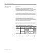
Table 5.D – Maximum TDUV Time (without Capacitor)
Control Voltage
Max. TDUV Time (secs)
400 A
800 A
110/120 V
0.2
0.2
220/240 V 1.0 1.0
If the undervoltage condition persists beyond the set delay time, the
contactor will be opened and an undervoltage fault or warning condition
w ill oc c ur (see Line Undervoltage and Table 4.F in Chapter 4).
Table 5.E – Maximum TDUV Time (with Capacitor)
Control Voltage
Max. TDUV Time (sec)
Capacitor
400A
800A
110/120V
2.0
2.0
1650uF - 80158-779-51-R
220/240V
2.0
2.0
330uF - 80158-779-52-R
*
Refer to Table 3.A for recommended fuse sizing.
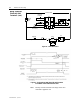
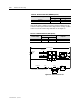
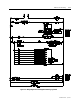
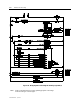
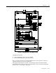
MOV
32
1
EC
-
+
4
TCO
12
11
AUX CCO
5
6
L1 L2/NG
+ -
STOP
START
OVERLOAD
CONTROL
POWER
FUSE
*
CONTROL POWER
M-IV
9 10
CLOSE
M-IV
15 16
CONTACTOR
STATUS
M
M-IV
M
CAPACITOR
Figure 5.8 – TDUV Control Circuit