
Manual

Description of Features 4-33
1503-UM054C-EN-P – June 2013
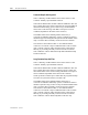
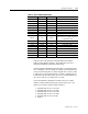
Table 4.F - Plus Fault/Warning Description
Fault/Warning Red LED Green LED Description
None Off Solid On Application Firmware Running
None Off Flash @ 0.25Hz Application Disable Jumper In
None Off Flash @ 0.50Hz Programming Base Unit(s)
None Off Off No power from IB or DeviceNet
Warning Off 2 Pulses RTC Fail
Warning Off 3 Pulses Line Undervoltage
Warning Off 4 Pulses Line Overvoltage
Warning Off 5 Pulses Extended Close Time (See Table 4.G)
Warning Off 6 Pulses
DeviceNet Power Loss
(only if Power was available on power up
– need historical value)
Warning Off 7 Pulses MC Altitude Setting Warning
Fault Solid On Undefined In RESET mode or F/W Crash
Fault 2 Pulses Off POST failure –RAM
Fault 5 Pulses Off Appl. Programming Error – CRC
Fault 6 Pulses Off RS485 Comm Fault (IB Fault)
Fault 7 Pulses Off IB1 Power Loss
Fault 8 Pulses Off Coil Open
Fault 9 Pluses Off System Lock Up
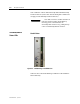
Table 4.F shows the operation of the Plus Status LED and the
faults/warnings that they indicate. This table makes use of two
methods of indicating a particular fault/warning.
The first method will flash the particular LED at a certain frequency
rate. Flashing at a rate of 0.25Hz, for example, means that the LED
will cycle from being off to on and to off again in 4 seconds, so that
it will be on for 2 seconds and off for 2 seconds. A flashing rate of
2.0Hz means that the LED will be on for 0.25 seconds and then off
for 0.25 seconds for a cycle time of 0.5 seconds.
The second method of indication is to flash a LED for a certain
number of pulses and then incorporate a pause in the cycle. The
pattern for a ‘2 Pulses’ pattern will be as follows:
1 – maintain LED on for 0.5 seconds
2 – maintain LED off for 0.5 seconds
3 – maintain LED on for 0.5 seconds
4 – maintain LED off for 0.5 seconds
5 – maintain LED off for 2 seconds
6 – repeat 1