
Manual


3-4 Installation
1503-UM054C-EN-P – June 2013
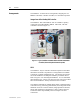
It is recommended the user interface with the IntelliVAC Plus using
interposing relays if possible. In the event that the IntelliVAC Plus
must be interfaced to a Solid State Output consult Table 3.A for
allowable leakage current values.
Table 3.A – Input Circuit Specifications
MOV
32
1
EC
-
+
4
TCO
12
11
AUX CCO
5
6
L1 L2/NG
+ -
STOP
START
OVERLOAD
CONTROL
POWER
FUSE
*
7 8
OPEN
16
15
CONTACTOR
STATUS
M
M-INTELLIVAC
M
CAPACITOR
(OPTIONAL)
+ -
9 10
CLOSE
14
13
MODULE
STATUS
CONTROL POWER
INPUT POWER
CONFIGURATION
DIP SWITCHES
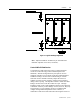
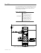
Figure 3.3 – IntelliVAC Typical Schematic (Electrically Held Vacuum Contactor)
Command Inputs
AC – 70 to 240 V rms
DC – 70 to 250 V
Maximum on state current for input circuit:
11mA
AC
@ 276 V AC, 60Hz, T
A
= 60°C
2.4mA
DC
@ 276 V DC, T
A
= 60°C
Minimum on state current for input circuit:
2.5mA
AC
@ 74 V AC, 60Hz, T
A
= 60°C
1.2 mA @ 68 V DC, T
A
= 60°C
Maximum off state current for input circuit:
1.9 µA @ 20 V AC, 60 Hz, T
A
= 60°C
900 µA @ 60 V DC, T
A
= 60°C