
Manual

DeviceLogix 9-27
1503-UM054C-EN-P – June 2013
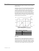
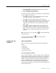
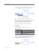
Figure 9.16 – Input Forced Indication
Forcing Outputs
The following list describes the output force options.
Table 9.J – Output Forcing
Ouput Force Option Description
Force On
Forces the input ON.
Force Off Forces the input OFF.
Remov e Force
Returns control of the input to the hardware device and
turns the instruction color back to white.
Clear Fault
When a device supports latching of faults, this selection
clears a hardw are output fault indication (for example, off-
wire or short circuit).
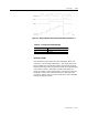
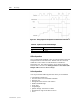
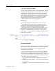
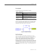
Figure 9.17 shows the result of placing a force on an output. When
force, an output element turns yellow with a red triangle indicator
and the status value reflects the force state chosen.
Figure 9.17 – Output Force Indication
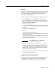
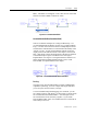
Dual Function Inputs
There are several bits which exhibit special behavior for a logic
engine. These bits consist of two “tags” to be used in the execution
of logic. There is an input tag and an output tag. Stimulus is
connected to the output tag which then controls the status of the
input tag. The purpose for this is to allow a user to assign an
important bit such as “stop status” to a hardware input so that when
reviewing the logic the user will be able to use the “stop status” bit
as opposed to the “DLX input 1” bit. This is to help a user create his
logic in a way which is easier to follow. See the example below for
c larific ation: