
Manual

8-6 Configuration/Programming
1503-UM054C-EN-P – June 2013
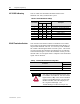
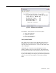
MC RS485 Addressing This set of DIP switches defines the RS485 address of the
IntelliVAC MC unit(s) within an MC system.
Table 8.H – MC RS485 Address Settings
MC Address
DIP S1
Description
1 2 3
0 OFF OFF OFF Not allowed – allocated to Advanced Module
1
OFF
OFF
ON
Not allowed – allocated to IB1 module
2 OFF ON OFF Valid MC Address
3
OFF
ON
ON
Valid MC Address
4
ON
OFF
OFF
Valid MC Address
5 ON OFF ON Valid MC Address
6 ON ON OFF Invalid MC Address
7
ON
ON
ON
Invalid MC Address
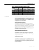
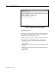
RS485 Termination Resistor This one DIP switch defines whether a termination resistor will be
inserted between the RS485A and RS485B differential data lines on
the particular IntelliVAC MC unit. It is used only on the IntelliVAC
MC module with the highest address in an MC system. This resistor
provides a load for the transmitter such that there are no reflections
of the transmitted signal. In effect the termination resistor provides
the load with a received signal which is a duplicate of the transmitted
signal, with no distortion.
Table 8.J – RS485 Termination Resistor Configuration
R
TERMINATION
DIP S1
6
Termination resistor not inserted OFF
Termination resistor inserted ON
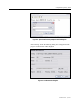
A T T E N T I O NA T T E N T I O N
In an MC system the termination resistor must
be installed in the IntelliVAC MC unit with the
highest address, only. If the correct termination
resistor is not installed, then an ‘Incorrect MC
RTERM Ins talled’ fault w ill be dis played on
the 7-segment LED display. (See
Troubleshooting Procedures in Chapter 10).