
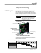
Owner's manual

Monitoring and Troubleshooting 5-5
1503-UM051D-EN-P – June 2013
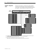
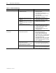
Table 5.C – Module Troubleshooting (cont.)
Problem or Trip Indicated Indication of the following conditions Possible Solutions
• Motor Protection activated • Investigate and reset.
• Stop command initiated • Verify circuit
• Module Status LED ‘Red’ • Undervoltage fault (no TDUV), control voltage
dipped below trip point. Cycle control power
to reset. Verify voltage levels are 110 to 240
VAC, 110 to 250 VDC.
• With external capacitor and TDUV feature
activated, undervoltage condition for longer
than programmed TDUV time. Undervoltage
fault activated. Cycle control power to reset.
• Module Status LED ‘Green’ and Contactor
Status LED ‘Red Flash 2’ (Series B only)
• Contactor Status feedback between Terminals
11 and 12 on the IntelliVAC has closed. The
IntelliVAC will de-energize the coil, thinking
the contactor has opened for other reasons.
Contactor opens during operation
• Both status LEDs ‘Off’ • Check control voltage and internal control
fuse. (Refer to Figure 4.1 for location.)
• Module Status LED ‘Red’ and Contactor
Status LED ‘Yellow’ (Series A, with firmware
2.001 or newer)
• Check control power to ensure that it has not
dipped below minimum (see Table 5.D).
Contactor does not open
(mechanical latch only)
• Module Status LED ‘Yellow’ and Contactor
Status LED ‘Yellow’ (Series B, with firmware
2.001 or newer)
• Trip mechanism is damaged. Inspect and
replace if needed.
• Check for loose connections in the control
circuit.
Refer to Tables 5.A or 5.B for definition of Module LED states.
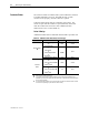
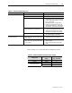
Table 5.D – Minimum IntelliVAC Operational Supply Voltages
Voltage Level
Contactor Rating
(Amps)
Minimum Voltage
(VAC, 47 to 63 Hz)
Pick-Up 400/800 95
Drop-Out 400/800 75
400 70
Trip (Mechanical Latch)
800 80