
Owner's manual
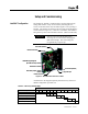

5-4 Monitoring and Troubleshooting
1503-UM051D-EN-P – June 2013
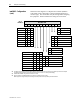
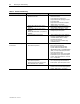
Table 5.C – M
odule Troubleshooting
Problem or Trip Indicated Indication of the following conditions Possible Solutions
• Motor Protection activated
• Both Status LEDs ‘Off’
• Investigate and reset
• Check Control Power
• Loose connections in control circuit
• Verify IntelliVAC power input plug is in place
and properly seated
• Verify internal control fuse has not opened
(Refer to Figure 4.1 for location)
• Module Status LED ‘Red’ upon power up
(Series A)
• IntelliVAC faulted. Cycle control power to
reset. Replace IntelliVAC if unsuccessful.
• Module Status LED ‘Red’ upon power up
(Series A)
• Module Status ‘Red Flash 1’ upon power up
(Series B)
• Improper setting of dip switches. Check
settings and cycle control power.
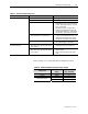
Contactor does not energize
• Loose connection in control circuit. • Verify contactor auxiliary set up. Reference
Publication 1502-UM052A-EN-P (400A) or
1502-UM051B-EN-P (800A) – Auxiliary
Contact Set-up Procedure.
• Verify circuit continuity (is contactor plug
connected properly?)
• Module status LED ‘Red’ and Contactor
Status LED ‘Off’ (Series A)
• Coil damaged or connections are loose.
Repair and cycle control power.
• Auxiliary Contact Assembly improperly
adjusted. Reference Publication 1502-
UM052A-EN-P (400A) or 1502-UM051B-EN-P
(800A) – Auxiliary Contact Set-up Procedure.
Cycle control power to reset.
• Undervoltage fault (no TDUV), control voltage
dipped below trip point. Cycle control power
to reset. Verify voltage levels are 110 to 240
VAC, 110 to 250VDC
• Module status LED ‘Red’ and Contactor
Status LED ‘Off’ (Series A)
• Module status LED ‘Green’ and Contactor
Status LED ‘Red Flash 1’ (Series B)
• Armature Plate obstructed from closing to coil
face. Verify no foreign material behind the
armature plate. Cycle control power to reset.
Contactor closes momentarily and
will not reclose.
• Both status LEDs ‘Off’ • Check internal control fuse. Verify IntelliVAC
operation in test mode before applying Medium
Voltage. (Refer to Fig. 4.1 for location.)