
Owner's manual


3-8 Installation and Wiring
1503-UM051D-EN-P – June 2013
Connections (cont.)
Interface Connections
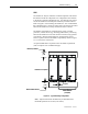
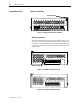
Ground Connection
L2/NL1
CONTACTOR STATUS OUTPUT (N.O.)
MODULE STATUS OUTPUT (N.O.)
POWER INPUT
13 161514
Ground Connection
L2/NL1
CONTACTOR STATUS OUTPUT (N.O.)
MODULE STATUS OUTPUT (N.O.)
POWER INPUT
13 161514
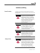
Figure 3.6 – Bottom side connections (Series B)
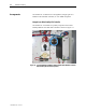
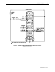
Interface Connections
All other control interface connections are made at a twelve-pole
connector located on the top of the module. Refer to Figure 3.7 or
3.8 and Table 3.B for connections. Refer to the Wiring Guidelines
section in this chapter for guidance in making connections to the
control circuit.
CONTACTOR INTERFACE
11 12891056 72341
EX. CAP.
Ground Connection
CONTACTOR INTERFACE
11 12891056 72341
EX. CAP.
Ground Connection
Figure 3.7 – Top side connections (Series A)
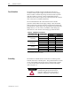
CONTACTOR INTERFACE
11 12891056 72341
EX. CAP.
Figure 3.8 – Top side connections (Series B)