IntelliVAC™ Contactor Control Module Bulletin 1503VC User Manual
Important User Information Read this document and the documents listed in the Additional Resources section about installation, configuration, and operation of this equipment before you install, configure, operate, or maintain this product. Users are required to familiarize themselves with installation and wiring instructions in addition to requirements of all applicable codes, laws, and standards.
Table of Contents Product Description Chapter 1 Introduction ..............................................................................1-1 Description ...............................................................................1-1 IntelliVAC Features ......................................................... 1-2 IntelliVAC Versions ......................................................... 1-3 Specifications ..........................................................................
ii Table of Contents Setup and Commissioning Chapter 4 IntelliVAC Configuration ....................................................... 4-1 Monitoring & Troubleshooting Chapter 5 Introduction ............................................................................. Module Status ......................................................................... Contactor Status ...................................................................... Series B Design .............................................
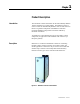
Chapter 1 Product Description Introduction This document contains information for the Allen-Bradley Bulletin 1503VC IntelliVAC™ control module. The Bulletin 1503VC is used to control the Allen-Bradley Bulletin 1502 vacuum contactors that are a significant component of the Bulletin 1500/1900 Centerline Medium Voltage Motor Controllers offered by Rockwell Automation.
1-2 Product Description Description (cont.) External Capacitor (Optional) Coil Power Supply Current Regulator Control Power Supply C C IGBT Coil Switching Close Signal Contactor Coil(s) Interface Coil Current Transducer Input Power Conditioning Supply Voltage 110-240 VAC or 110-250 VDC Vacuum Contactor Trip Coil Command Inputs Open Signal Vacuum Contactor Auxiliary Micro Controller CC Aux.
Product Description 1-3 IntelliVAC Features (cont.
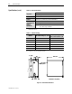
1-4 Product Description Specifications Mounting & Connections The IntelliVAC control modules are mounted using two (2) screws (see Figure 1.3). They are typically located in the low voltage control panel of the medium voltage controller (Bulletin 1500/1900 controllers, in the case of Rockwell Automation). IntelliVAC is interfaced to the Bulletin 1502 vacuum contactors using a “quick” connector, located at the module, a wire harness and “quick” connector at the contactor.
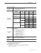
Product Description 1-5 Table 1.A – Electrical Ratings Main Input Voltage (L1 to L2/N) AC – 110 to 240 V rms, +10/-15%, 47 to 63 Hz DC – 110 to 250 V, +10/-15% Description Main Input Current (L1 to L2/N) Contactor Ratings Control Voltage (Amps) (AC or DC) 400/800 120/240 25 A peak (1/2 cycle) 25 A peak Idle Current (Maximum without contactor coil energized) 400/800 120/240 125 mA 35 mA Hold Current (maximum) 400/800 120/240 300 mA 100 mA 120 4.6 A 3.6 A 240 3.4 A 3.3 A 120 11.
1-6 Product Description Specifications (cont.) Table 1.B – Mechanical Ratings Temperature Operating: 0° to 60°C ambient at the control module X Non-Operating: -40° to 85°C Altitude -1000 to 5000 meters Pollution Pollution level II (as defined by UL 840 and IEC 60664-1) Humidity Class II Shock and Vibration (Operational) X Shock – 15 g peak, 11 milliseconds Vibration – 10 to 57 Hz, 0.015 inch displacement peak to peak - 57 to 150 Hz, 2.
Chapter 2 Receiving and Storage Receiving Upon receiving the controller, remove the packing and check for damage that may have occurred during shipping. Report any damage immediately to the claims office of the carrier. NOTE: If the IntelliVAC module is an integral component of a complete MV controller (Bulletin 1500/1900), special receiving and handling instructions will apply. For details, refer to the service manual provided with the equipment.
2-2 Receiving and Storage (This page is intentionally left blank.
Chapter 3 Installation and Wiring General Precautions In addition to the precautions listed throughout this manual, the following statements, which are general to the system, must be read and understood. ATTENTION ATTENTION ATTENTION Safety and Codes ATTENTION The controller contains ESD (electrostatic discharge) sensitive parts and assemblies. Static control precautions are required when installing testing, servicing, or repairing the assembly.
3-2 Installation and Wiring Arrangements The IntelliVAC is offered in two arrangements, Integral (part of a Bulletin 1500/1900 MV controller) or as an OEM component. Integral to an Allen-Bradley MV Controller The IntelliVAC is available as a primary component of an AllenBradley Bulletin 1500/1900 MV controller as shown in Figure 3.1. Figure 3.
Installation and Wiring 3-3 OEM The IntelliVAC may be ordered as an OEM component. This allows the OEM to mount the components in a configuration most suitable to the motor controller equipment layout. Care must be exercised to ensure the IntelliVAC has adequate ventilation provided around it. Refer to Figure 3.2 for mounting the IntelliVAC. It is recommended that a minimum of 1.5 inches (38.1mm) of free air space be provided between the IntelliVAC and any solid barrier above or below.
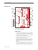
3-4 Installation and Wiring Arrangements (cont.) CONTROL POWER * M-INTELLIVAC CONTROL POWER FUSE 7 + 9 + OVERLOAD STOP - 8 OPEN CLOSE START 16 - 10 CONTACTOR STATUS 15 14 MODULE STATUS CAPACITOR (OPTIONAL) M 13 1 EC 2 + TCO 4 3 11 AUX 12 CCO 6 5 MOV M CONFIGURATION DIP SWITCHES L1 ∗ INPUT POWER G L2/N Refer to Table 3.A for recommended fuse sizing. Figure 3.
Installation and Wiring 3-5 CONTROL POWER M-INTELLIVAC * CONTROL POWER FUSE 7 + 9 + OVERLOAD STOP - 8 OPEN - 10 CLOSE START 16 CONTACTOR STATUS 15 14 MODULE STATUS CAPACITOR (OPTIONAL) M 13 1 EC 2 + TCO 4 3 11 AUX 12 CCO 6 5 MOV M CONFIGURATION DIP SWITCHES L1 P' P ∗ INPUT POWER G L2/N EMC FILTER G N' N Refer to Table 3.A for recommended fuse sizing. Figure 3.
3-6 Installation and Wiring Fuse Protection The IntelliVAC module requires external fuse protection to coordinate with the power supply and contactor. The fuse ratings shown in Table 3.A allow the passage of inrush currents expected when the contactor is closed, or from recommended external capacitors for the TDUV option. They will also protect the contactor coils in the event of a module malfunction. The recommended fuses have been tested to ensure reliable protection of the module.
Installation and Wiring Connections 3-7 There are three green connectors on the IntelliVAC module for connections to the control circuitry. Connector plugs are provided with the module. If additional plugs are required, refer to Chapter 6, Spare parts. Control Power The IntelliVAC can accept either AC or DC control power. Refer to Table 1.A for acceptable input power and control signal ratings.
3-8 Installation and Wiring Connections (cont.) Interface Connections Ground Connection 13 14 15 16 L1 L2/N CONTACTOR STATUS OUTPUT (N.O.) MODULE STATUS OUTPUT (N.O.) POWER INPUT Figure 3.6 – Bottom side connections (Series B) Interface Connections All other control interface connections are made at a twelve-pole connector located on the top of the module. Refer to Figure 3.7 or 3.8 and Table 3.B for connections.
Installation and Wiring 3-9 Table 3.B – Terminal Assignments for IntelliVAC Interface Connections X Terminal No.
3-10 Installation and Wiring Wiring Guidelines Electrically Held Contactors The IntelliVAC can be applied with two- or three-wire control circuits. The control system utilized will determine the configuration of the input wiring. Consider the following input and output for the type of control used: • Terminals 9 and 10 • Terminals 15 and 16 Close Contactor Contactor Status In either case, the CLOSE input must receive a maintained voltage high to keep the contactor closed. Note: 1.
Installation and Wiring 3-11 Two-Wire Control If using two-wire control, the CLOSE contactor input is maintained high using a single contact. Momentarily opening this input will cause the IntelliVAC to open the contactor. Maintaining the contact will provide a CLOSE command to IntelliVAC (given that all permissives are satisfied). If a fault occurs, in addition to cycling control power to the IntelliVAC module, the CLOSE command must be removed for a minimum of 4 seconds, before being re-applied.
3-12 Installation and Wiring Wiring Guidelines Electrically Held Contactors (cont.) Three-Wire Control If using three-wire control, the CLOSE contactor input is maintained high using two contacts. Momentarily opening this input will cause the IntelliVAC to open the contactor. Momentarily closing the START contact will provide a CLOSE command to IntelliVAC (given that all permissives are satisfied). In this configuration, the STATUS output acts as a seal-in contact.
Installation and Wiring 3-13 15mS CLOSE COMMAND TO MICRO DEBOUNCE 80mS 15mS DEBOUNCE Y 5mS CLAMP DELAY MICRO OUTPUT TO CLOSE COIL 200mS CLOSE LEVEL OF CURRENT TO CLOSE COIL CONTACTOR STATUS RELAY OUTPUT SELECTABLE DROP OUT TIME (0 TO 190mS) 60mS ACKNOWLEDGE WINDOW X MODULE STATUS RELAY OUTPUT CONTACTOR PICK UP 90mS (@120VAC) NATURAL CONTACTOR DROP OUT 30mS CONTACTOR AUXLIARY INPUT TO MICRO X Contact status relay closes on request to close.
3-14 Installation and Wiring Wiring Guidelines Mechanically Latched Contactors IntelliVAC control may be used for mechanically latched contactors. A momentary control signal is needed to close the contactor, and a second momentary control signal is needed to open the contactor. The momentary open/close commands must be at least 50 milliseconds in duration. Refer to Figure 3.12 for a typical mechanical latch control scheme. Note: 1.
Installation and Wiring Mechanically Latched Contactors 3-15 Capacitor Trip The IntelliVAC can be configured to provide capacitor trip functionality with mechanically latched contactors. A capacitor must be connected to the IntelliVAC (terminals #1 and #2) in order to provide this capability. The capacitor provides control power for the IntelliVAC as well as stored energy to trip the contactor. Maximum recommended capacitor size is 1650 µF for 120V control or 330 µF for 240V control.
3-16 Installation and Wiring CONTROL POWER M-IV OPEN * CONTROL POWER FUSE OVERLOAD 7 + - 8 OPEN M CAPACITOR M 1 EC 2 + TCO 4 3 MOV TC MOV 11 AUX 12 L1 P' P CLOSE M-IV CCO G EMC FILTER G 6 5 CC L2/N N' N M-IV 9 + - 10 ∗ Refer to Table 3.A for recommended fuse sizing. CLOSE Figure 3.
Installation and Wiring Motor Jogging Control 3-17 When used with electrically held contactors, the IntelliVAC allows close commands every six seconds. This is to ensure the rated contactor duty cycle of 600 operations per hour is not exceeded. For motor jogging operations, the second control input, or OPEN command, will close the contactor for as long as the input is present, and open the contactor when the input is removed. (Refer to Figure 3.14.
3-18 Installation and Wiring Time Delay Undervoltage The IntelliVAC can be configured to provide time delay undervoltage (TDUV) protection. The feature is available to keep electrically held contactors closed during a voltage dip or brief power loss. This option may require the addition of a capacitor (see below). Refer to Chapter 6 for typical capacitor sizing. The capacitor is connected to terminals 1(-) and 2(+) of the IntelliVAC. (Refer to Figure 3.15.) Table 4.
Chapter 4 Setup and Commissioning IntelliVAC Configuration The IntelliVAC module is configured for a specific application by setting DIP switches. They are accessed by loosening the two screws on the front of the unit, and removing the cover by sliding it forward. The switches are found on the front edge of the IntelliVAC circuit board (see Figure 4-1). There are 12 switches, with number 1 being at the top next to the mini DIN connector. (Refer to Table 4.B).
Setup and Commissioning 4-2 IntelliVAC units shipped in a complete MV controller (Bulletin 1500/1900) will be configured to suit the installed application (i.e. contactor type). The user should verify the settings before energizing the equipment. Table 4.B defines the settings for each switch. IntelliVAC Configuration (cont.
Chapter 5 Monitoring and Troubleshooting Introduction The IntelliVAC module has two light emitting diodes (LEDs) and relay outputs to indicate the status of the contactor and the module. The LEDs are visible on the front of the module and the relay outputs are accessed on the bottom front of the module. Figure 5.1 – IntelliVAC LEDs Module Status The Module Status is indicated with a Green LED if the module is functioning properly and has a valid configuration.
5-2 Monitoring and Troubleshooting Contactor Status The Contactor Status is indicated with a yellow LED that is off until a CLOSE command is received. The LED will stay on if the contactor closes properly, until the contactor is opened. Contactor Status output relay has a normally open contact. The contact is open when the contactor is open (LED off), and closed when the contactor has received a close command (for 200 milliseconds) or if it is closed (LED on).
Monitoring and Troubleshooting 5-3 Table 5.
5-4 Monitoring and Troubleshooting Table 5.C – Module Troubleshooting Problem or Trip Indicated Contactor does not energize Indication of the following conditions • Motor Protection activated • Both Status LEDs ‘Off’ Possible Solutions • • • • • • Module Status LED ‘Red’ upon power up (Series A) • Module Status LED ‘Red’ upon power up (Series A) • Module Status ‘Red Flash 1’ upon power up (Series B) • Loose connection in control circuit. • • • • Contactor closes momentarily and will not reclose.
Monitoring and Troubleshooting 5-5 Table 5.C – Module Troubleshooting (cont.
5-6 Monitoring and Troubleshooting (This page is intentionally left blank.
Chapter 6 Spare Parts Spare Parts List IntelliVAC (electrically held) Series A IntelliVAC (mechanical latch) Series A IntelliVAC (electrically held and mechanical latch) Series B 1503VC-BMC1 1503VC-BMC2 Internal Fuse: 6.3 A, 250 V (Littlefuse 21506.
6-2 Spare Parts 1503-UM051D-EN-P – June 2013
Appendix A Typical Contactor Drop-out Times The contactor drop-out times shown in the following table are typical values used when the power fuses are provided as part of a complete MV controller from Rockwell Automation. The recommendations are based on Ferraz Shawmut power fuses. Other fuse types may require alternate drop-out time settings. Table A.
A-2 Typical Contactor Drop-out Times Table A.1 – Contactor Drop-out Times (cont.) Fuse Rating Voltage 7200 8250 Contactor Drop-out Time (msec) Current 2R 3R 4R 6R 9R 12R 18R 24R 2X18R 2X24R 20E 30E 40E 50E 65E 80E 100E 125E 150E 175E 200E 400A 800A 50 50 75 150 130 50 50 Fuse not suitable for use with 400A contactor.
Medium Voltage Products, 135 Dundas Street, Cambridge, ON, N1R 5X1 Canada, Tel: (1) 519.740.4100, Fax: (1) 519.623.8930, www.ab.com/mvb Publication 1503-UM051D-EN-P – June 2013 Supersedes Publication 1503-UM051C-EN-P – January 2006 Copyright © 2013 Rockwell Automation, Inc. All rights reserved. Printed in Canada.