Medium Voltage CONTROLLER INSTALLATION INSTRUCTIONS Adjustment to Interlocking Mechanism 400A Framed Interlocked Contactor Kit Bulletin 1503FR
Important User Information Read this document and the documents listed in the Additional Resources section about installation, configuration, and operation of this equipment before you install, configure, operate, or maintain this product. Users are required to familiarize themselves with installation and wiring instructions in addition to requirements of all applicable codes, laws, and standards.
Table of Contents General Information Chapter 1 Document Scope ........................................................................... Product Identification .................................................................... Interlock Adjustment 1-1 1-1 Chapter 2 Product Description ....................................................................... Ratings ........................................................................................... Interlock Adjustment .........................
ii Table of Contents 1503FR-IN001B-EN-E – June 2013
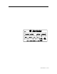
Chapter 1 General Information Document Scope This User Manual pertains to the Rockwell Automation Bulletin 1503FR Frame Interlock Contactor Kit. This document should be used along with publication 1502-UM051_-EN-P. Product Identification A nameplate is attached to the frame of this structure (see Figure 1.1). Refer to the nameplate for information such as series number, section number, voltage and amperage rating. Figure 1.
1-2 General Information 111 1503FR-IN001B-EN-E – June 2013
Chapter 2 Product Description The Allen-Bradley Bulletin 1503FR Frame Interlocked Contactor Kit uses electrically held contactors, 400 amp, and is rated from 2400 to 7200 volts. The Bulletin 1503FR can be used on reversing or two speed application. The mechanical interlock prevents the possibility of both contactors being energized at the same time. Each Bulletin 1503FR Kit is also supplied with two IntelliVAC control modules, to control the operation of each contactor.
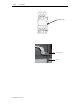
2-2 Produc t Description Interlock Adjustment (cont.) Mechanical Interlock Figure 2.1 – Front View of Unit 2) At the top of the mechanical interlock is the interlock lever adjustment. (Figure 2.2) 5/16” Adjustment Nut Lock Nut Figure 2.2 – Top Interlock Lever 3) 1503FR-IN001B-EN-E – June 2013 To adjust the interlock, first loosen the lock nut and then the 5/16” Adjustment nut. (Figure 2.2) At the bottom of the interlock assembly is the interlock cam. (Figure 2.
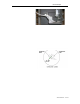
Product Description 2-3 Figure 2.3 – Interlock Cam 4) Manually move the top mounted interlock lever so the top mounted contactor is in the closed position. The gap between the interlock cam and the interlock lever should be between .031” and .052”. Note: Use a ¼” flat washer as required to space interlock lever and cam to obtain a proper clearance. (Figure 2.4) Figure 2.
2-4 Produc t Description Interlock Adjustment (cont.) Note: Use a ¼” flat washer as required to space interlock lever and can to obtain a proper clearance. (Figure 2.5) Figure 2.5 – Clearance Between Cam and Lever: Contactor Open 1503FR-IN001B-EN-E – June 2013 7) Use two lock nuts to adjust the space clearance.