
Installation Manual User Manual


Chapter 2
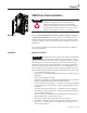
Component Installation for 400A Equipment
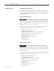
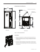
Component Layout Refer to the following diagram to determine the location of the OEM
components relative to each other.
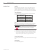
The mounting location of the trailer fuse block varies
depending on the type of power fuses used by the unit.
Figure 2.1 shows the component confi guration for units
using clip-on power fuses and Figure 2.2 shows the compo-
nent confi guration for units using bolt-on power fuses.
20.89
[531]
9.53
[242]
1.00
[25]
10.50
[267]
4.44
[113]
18.82
[478]
1.20
[30]
10.80
[274]
8.96
[228]
18.55
[471]
11.87
[301]
22.85
[580]
7.33
[186]
1.19
[30]
12.05
[306]
4.88
[124]
39.78
[1010]
37.11
[943]
Lower Mounting Surface
Front Mounting Surface
Rear Mounting Surface
4.60
[117]
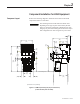
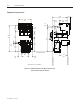
(All dimensions in inches [millimeters])
Figure 2.1 – OEM Component Layout (Clip-on Power Fuses)
(Frame and other parts not shown)
1503-IN050E-EN-P – June 2013
I M P O R T A N TI M P O R T A N T