
Installation Manual User Manual


2-24 Component Installation
1503-IN050E-EN-P – June 2013
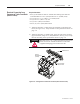
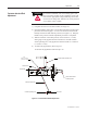
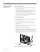
Incoming Line Connections Mounting hardware is suitable for use with lugs incorporating two-hole
NEMA drilling. Secure incoming cables to line terminals of the isolation
switch with suitable lugs and ½ in. (M12) hardware. Torque the hardware
according to the specifi cations shown on page 1-4.
Cable size should not exceed 1-500 or 2-250 MCM per phase.
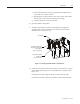
Attach Incoming Line Cables Here
Figure 2.22 – Isolation Switch Incoming Line Connections (Rear View)
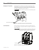
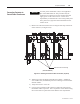
Load Connections Secure load cables to load terminals of contactor using suitable lugs and
3/8 in.(M10) hardware. Torque the hardware according to the specifi cations
shown on page 1-4.
It is the user’s responsibility to determine a suitable means
of completing the power connection from the contactor
to the motor ie. current transformers, power fuses, etc.
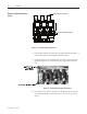
Load Terminals
Figure 2.23 – Load Terminals - 400 A Contactor (Rear View)
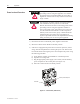
I M P O R T A N TI M P O R T A N T
I M P O R T A N TI M P O R T A N T