
Installation Manual User Manual


Component Installation 2-23
1503-IN050D-EN-P – June 2012
Required Hardware:
• three (3) horizontal bus links or suitable cable and lugs (bus links are
recommended to be 1/4 in. (6mm) thick and 1 in. (25mm) wide)
• six (6) 3/8-16 in. x 1 in. (M10 x 1.5 x 25mm) bolts
• six (6) 3/8-16 in. (M10 x 1.5) nuts
• six (6) 3/8 in. (M10) lock washers
• twelve (12) 3/8 in. (M10) fl at washers
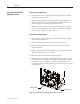
1) Attach the bus links or cables to the line terminals on the trailer fuse
block (see Figure 2.21). Torque the bolts to the specifi cations shown on
page 1-4.
2) Attach the bus links, or suitable cable, to the line side of the contactor
(upper terminals) using 3/8 in. (M10) hardware. (See Fig. 2.21) Torque
the bolts according to the specifi cations shown on page 1-4.
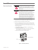
Maintain at least 3 in. (76 mm) clearance between power
phase connections. Insuffi cient distance could cause
equipment damaging power faults in the unit.
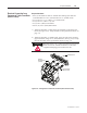
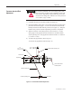
Figure 2.21 – Linking Trailer Fuse Block to Contactor (Bolt-on Power Fuses)
A T T E N T I O NA T T E N T I O N
Electrical Connection from
Contactor to Trailer Fuse Block
(Bolt-on Fuses)
Trailer Block Fuse
Contactor
Attachment Point
(Line Side)
Trailer Fuse Block
Attachment Point