
Installation Manual User Manual
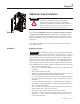
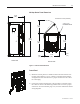
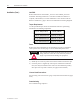
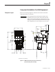
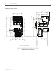

Table of Contents
Chapter 1 OEM Starter Frame Installation
Receiving ......................................................................................... 1-1
Installation ....................................................................................... 1-1
Standards and Codes ................................................................. 1-1
Imperial Tool Requirements ...................................................... 1-2
Metric Tool Requirements ......................................................... 1-2
Starter Frame Dimensions ......................................................... 1-3
Control Panel ............................................................................. 1-3
Torque Requirements ................................................................ 1-4
Fuses .......................................................................................... 1-4
Line and Load Connections ...................................................... 1-4
Commissioning ......................................................................... 1-4
Chapter 2
Component Installation
Component Layout .......................................................................... 2-1
Mounting Isolation Switch Handle Module .................................... 2-3
Mounting Isolation Switch and Trailer Fuse Block ......................... 2-5
Power Fuses ..................................................................................... 2-7
Contactor ........................................................................................ 2-10
Control Panel ................................................................................. 2-10
IntelliVAC .................................................................................... 2-10
Typical Electrical Diagrams for 400A FVNR Controller with
Electro-Mechanical Control and Electrically Held
Contactor, 120VAC ........................................................... 2-11
Electro-Mechanical Control and Mechanical Latch Contactor . 2-12
IntelliVAC Control and Electrically Held Contactor ............ 2-13
IntelliVAC Control and Mechanical Latch Contactor .......... 2-14
Door Interlock Assembly ............................................................... 2-15
Connecting Isolation Switch to Isolation Switch Handle .............. 2-17
Connecting Contactor to Isolation Switch Handle ........................ 2-18
Electrical Connection From Contactor to Trailer Fuse Block
(Clip-on Fuses) ......................................................................... 2-21
Electrical Connection From Contactor to Trailer Fuse Block
(Bolt-on Fuses) ......................................................................... 2-22
Incoming Line Connections ........................................................... 2-24
Load Connections .......................................................................... 2-24
Connecting Contactor to Control Power Transformer ................... 2-25
1503-IN050E-EN-P – June 2013