Component Installation 2-11
1503-IN050E-EN-P – June 2013
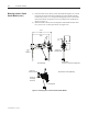
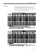
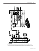
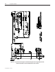
Figure 2.10 – Typical Schematic Diagram for 400 amp Full-Voltage Non-Reversing (FVNR) Controller
with Electro-Mechanical Control and Electrically Held Contactor, 120 V AC (Normal Drop-out Time)