OEM Starter Frame and Components Bulletin 1503 2400 to 7200 volts Installation Manual
Important User Information Read this document and the documents listed in the Additional Resources section about installation, configuration, and operation of this equipment before you install, configure, operate, or maintain this product. Users are required to familiarize themselves with installation and wiring instructions in addition to requirements of all applicable codes, laws, and standards.
Table of Contents Chapter 1 OEM Starter Frame Installation Receiving ......................................................................................... 1-1 Installation ....................................................................................... 1-1 Standards and Codes ................................................................. 1-1 Imperial Tool Requirements ...................................................... 1-2 Metric Tool Requirements ..........................................
ii Table of Contents – Bulletin 1503 OEM Starter Frame and Components • Installation Manual Chapter 3 Adjustments for 400A Equipment Door Interlock Circumvention ......................................................... 3-1 Power Lock-out Procedure .............................................................. 3-2 Contactor Interlock Rod Adjustment ............................................... 3-5 Isolation Switch Ground Adjustment...............................................
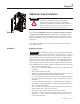
Chapter 1 OEM Starter Frame Installation ATTENTION Receiving Read this document before performing any installation procedures or adjustments. Observe all applicable safety procedures when working on the equipment. Complete all installation procedures before connecting the incoming line cable. Failure to do so may result in damage to the equipment or injury to personnel. Refer to General Handling Procedures for Medium Voltage Controllers – Publication MV-QS050_-EN-P.
1-2 OEM Starter Frame Installation Installation (Cont.) Standards and Codes (Cont.) The OEM starter frame assembly was fully tested and inspected at the factory. Unless damage from shipping is suspected, the commissioning procedures in Chapter 4 of this manual should be the only additional checks required for the unit. Imperial Tool Requirements Some components of this product incorporate Imperial hardware.
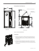
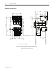
1-3 OEM Starter Frame Installation 400 Amp Starter Frame Dimensions 23.85 [606] All dimensions in inches [millimeters] 4 X ø.515 [13] MOUNTING HOLES 21.50 [546] 50.36 [1279] 21.17 [538] 27.22 [691] 21.89 [556] 0.97 [25] FRONT VIEW 3.83 [97] BOTTOM VIEW Figure 1.1 – Starter Frame Dimensions Control Panel 1) Mount the control panel in a suitable location. Be aware that the control plug wiring harness is 10 ft. (3 meters) in length.
1-4 OEM Starter Frame Installation Installation (Cont.) IntelliVAC Refer to Publication 1503-UM051_-EN-P or 1503-UM052_-EN-P for IntelliVAC mounting instructions. Note that a suitable wire harness is required (1503-WHxxx) to connect IntelliVAC to the vacuum contactor. Refer to “IntelliVAC”, page 2-10 for more information and wiring diagrams. Torque Requirements Use the specified torque values for all hardware whenever performing maintenance or attaching components. 1/4 in.
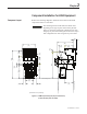
Chapter 2 Component Installation for 400A Equipment Component Layout Refer to the following diagram to determine the location of the OEM components relative to each other. IMPORTANT The mounting location of the trailer fuse block varies depending on the type of power fuses used by the unit. Figure 2.1 shows the component configuration for units using clip-on power fuses and Figure 2.2 shows the component configuration for units using bolt-on power fuses. 4.60 [117] 22.85 [580] 18.55 [471] 7.
2-2 Component Installation Component Layout (cont.) 4.60 [117] 22.85 [580] 18.55 [471] 7.33 [186] 12.05 [306] 1.19 [30] 8.96 [228] 39.78 [1010] 1.00 [25] 9.53 [242] 16.67 [423] 1.20 [30] 37.11 [943] 20.89 [531] 12.95 [329] Lower Mounting Surface 10.50 [267] (All dimensions in inches [millimeters]) Figure 2.2 – OEM Component Layout (Bolt-on Power Fuses) (Frame and other parts not shown) 1503-IN050E-EN-P – June 2013 11.87 [301] Rear Mounting Surface 4.88 [124] Front Mounting Surface 4.
2-3 Component Installation Mounting Isolation Switch Handle Module The handle is shipped in the OFF, or open, position. All instructions assume the handle remains in the OFF position during installation and adjustment procedures unless otherwise stated. IMPORTANT Required Hardware: • Six (6) ¼-20 x 0.5 in. (6.3 x 1.8 x 13mm Type B) self-tapping screws • One (1) 5/16 in. (M8 x 1.25) grounding wire screw Refer to the component layout shown in Figure 2.1 or 2.
2-4 Component Installation Mounting Isolation Switch Handle Module (cont.) 3) From the inside of the cabinet, insert the handle through the cut-out and line up the pilot holes with the pre-drilled holes in the handle assembly. Use four (4) ¼-20 (6.3 x 1.8 Type B) self-tapping screws to attach the front of the handle. Torque the screws according to the specifications shown on page 1-4. 4) Mark the location of the rear mounting tabs of the handle module. Drill two (2) 0.219-in. (5.
Component Installation 2-5 5) Install two (2) ¼-20 (6.3 x 1.8 Type B) self-tapping screws in the tabs at the end of the handle module to attach it to the rear of the cabinet. Torque the screws according to the specifications shown on page 1-4. IMPORTANT The rear mounting tabs may deform slightly when secured to the mounting surface. The deformation is normal and helps to reduce any gap between the handle module and the mounting surface.
2-6 Component Installation Mounting Isolation Switch and Trailer Fuse Block (cont.) Refer to the component layout shown in Figure 2.1 or 2.2 to determine the location of the trailer fuse block. Refer to Figure 2.6 to determine the location of the mounting holes for the trailer fuse block. 1) Drill four (4) 0.219 in. (5.5 mm) pilot holes at Location B as shown in Figure 2.6 for the trailer fuse block. 2) Attach the trailer fuse block using four (4) ¼-20 (4.8 x 1.6 Type B) self-tapping screws.
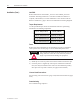
Component Installation Power Fuses 2-7 Ferraz-Shawmut medium voltage power fuses are recommeded for the Bulletin 1503. These motor fuses have been tested and meet the co-ordination requirements for the Bulletin 1502 vacuum contactor. The fuses many be purchsed from Rockwell Automation, Ferraz-Shawmut, or from a local distributor. The following part numbers are available. (See Figures 2.7 and 2.8 for dimensions of fuses.) Table 2.
2-8 Component Installation Power Fuses (cont.) (All dimensions in inches [millimeters]) Figure 2.
Component Installation 2-9 (All dimensions in inches [millimeters]) Figure 2.
2-10 Component Installation Contactor Refer to the following publications for the Bulletin 1502 Medium Voltage Contactor: • 400A – Publication 1502-UM050_EN-P ( Series D) • 400A – Publication 1502-UM052_EN-P (Series E) • 800A – Publication 1502-UM051_EN-P (Series E) These user manuals contain detailed information on installation, adjustment and maintenance for this product. Contactor Control Wire Plug Figure 2.
Component Installation 2-11 Figure 2.
2-12 Component Installation Figure 2.
2-13 CC Component Installation Figure 2.
2-14 Component Installation Figure 2.
Component Installation Door Interlock Assembly 2-15 When properly installed the door interlock assembly (see Figure 2.13), used in conjunction with the isolation switch, is designed to provide the following interlocking features: • • When the isolation switch handle is in the ON position, a pin on the handle overlaps the Z-clip to prevent the door from being opened.
2-16 Component Installation Door Interlock Assembly (cont.) All mounting hardware for the Door Interlock Assembly is supplied. Metric equivalents are provided should the user wish to substitute metric hardware. IMPORTANT 1) See Figure 2.15 for the mounting dimensions for the door interlock assembly. 2) Drill two (2) 0.172 in. (4.6 mm) pilot holes on the right side of the door for the Z-clip. 3) Drill two (2) 0.219 in. (5.5 mm) pilot holes on the front of the door for the cover catch mounting bracket.
Component Installation 2-17 7) Move the handle to the OFF position. Swing the door closed and inspect the position of the Z-clip with respect to the handle pin. 8) Set the Z-clip so that it is just above the handle pin. Do not set the Z-clip more than 0.125 in. (3 mm) above the pin. Tighten the screws. 9) Close the door and move the isolation switch handle to the ON position. If the handle will not move to the ON position, the cover catch is set too high and is not contacting the defeater lever.
2-18 Component Installation Connecting Isolation Switch to Isolation Switch Handle (cont.) Perform the handle mechanism connection with the handle in the OFF position. The isolation switch should be in the open position with the isolation switch blades resting against the ground bar. Refer to Figure 2.16. 1) Lengthen or shorten the threaded connecting rod until it lines up with the top hole on the isolation switch operating lever. 2) Insert a clevis pin through the holes and secure it with a cotter pin.
Component Installation 2-19 Required Hardware: (all hardware supplied) IMPORTANT Metric hardware is not supplied; however, metric equivalents are given should the user wish to substitute metric hardware • Two (2) 1/4 in. (M6) lock washers • Two (2) 1/4 in. (M6) flat washers • Two (2) 1/4-20 in. (M6 x 1.0) hex-head cap screws • One (1) 5/16-18 in. (M8 x 1.25) nylock nut • Two (2) 5/16 in. (M8) hex nuts • One (1) 5/16 in. (M8) lock washer • One (1) contactor operating lever • One (1) 5/16-18 x 20.5 in.
2-20 Component Installation Connecting Contactor to Isolation Switch Handle (cont.) 2-1/4-20 1.0) Hex. Cap Screws 2-1/4-20(M6 HexxHead Cap Head Screws 2-1/4 in. (M6) Lock Washers 2-1/4 in. Lock Washers 2-1/4 Flat Washers 2-1/4in. in.(M6) Flat Washers Contactor Interlock Rod Contactor Shaft Nylon Contactor Bushing Contactor Operating Lever Right Side View Figure 2.18 – Connecting Contactor to Isolation Switch Handle 5) Tighten the bottom nut up to the clevis.
Component Installation 2-21 Electrical Connection from Required Hardware: Contactor to Trailer Fuse Block • three (3) horizontal bus links or suitable cable and lugs (bus links are (Clip-on Fuses) recommended to be 1/4 in. (6mm) thick and 1 in. (25mm) wide) • three (3) 3/8-16 in. x 1 in. (M10 x 1.5 x 25mm) bolts • three (3) 3/8-16 in. (M10 x 1.5) nuts • three (3) 3/8 in. (M10) lock washers • six (6) 3/8 in. (M10) flat washers Supplied Hardware: • three (3) 5/16-18 x 1 in. bolts • three (3) 5/16 in.
2-22 Component Installation Electrical Connection From 1) Use the supplied 5/16 in. hardware to mount the bus link or suitable Contactor to Trailer Fuse Block cable to the trailer fuse block (see Figure 2.20). Torque the bolts to the (Clip-on Fuses) specifications shown on page 1-4. (cont.) IMPORTANT The trailer fuse block is equipped with 5/16-18 nuts. The supplied hardware, or equivalent, must be used to avoid damaging the thread in the nuts.
Component Installation 2-23 Electrical Connection from Required Hardware: Contactor to Trailer Fuse Block • three (3) horizontal bus links or suitable cable and lugs (bus links are (Bolt-on Fuses) recommended to be 1/4 in. (6mm) thick and 1 in. (25mm) wide) • six (6) 3/8-16 in. x 1 in. (M10 x 1.5 x 25mm) bolts • six (6) 3/8-16 in. (M10 x 1.5) nuts • six (6) 3/8 in. (M10) lock washers • twelve (12) 3/8 in.
2-24 Component Installation Incoming Line Connections Mounting hardware is suitable for use with lugs incorporating two-hole NEMA drilling. Secure incoming cables to line terminals of the isolation switch with suitable lugs and ½ in. (M12) hardware. Torque the hardware according to the specifications shown on page 1-4. IMPORTANT Cable size should not exceed 1-500 or 2-250 MCM per phase. Attach Incoming Line Cables Here Figure 2.
Component Installation Connecting Contactor to Control Power Transformer IMPORTANT 2-25 A control power transformer (CPT) is not supplied as part of the OEM starter kit. This procedure only describes how to connect wires to the contactor that will supply power to the control circuit. It is the user’s responsibility to determine the correct CPT, primary fuse sizes, power wire, lugs and current transformer for the control circuit.
2-26 Component Installation 1503-IN050E-EN-P – June 2013
Chapter 3 Adjustments for 400 Amp Equipment Door Interlock Circumvention IMPORTANT To ensure proper functioning of the isolation switch assembly, perform the following adjustments in the order they are presented. ATTENTION The door interlock mechanism is designed to prevent access to the medium voltage cell while the unit is energized. When the unit is in operation, do not circumvent this interlocking safety feature.
3-2 Adjustments Power Lock-out Procedure ATTENTION ATTENTION Always perform the power lock-out procedure before proceeding with servicing the equipment Use suitable personal protective equipment (PPE) per local codes or regulations. Failure to do so may result in severe burns, injury or death. The following procedure requires moving the isolation switch handle to the ON position. To avoid shock hazards, disconnect and lock out incoming power before proceeding with servicing the equipment.
Adjustments 3-3 e) Electrically operate the contactor by pushing the START button on the unit or at a remote location. f) Disengage the contactor and move the control switch to the NORMAL position. Disconnect the external power supply. g) Complete the Power Lock-out procedure 4) Open the medium voltage door. 5) Visually inspect that the isolation switch blades fully engage the grounding pins on the grounding bar. The isolation switch shutters should be closed (see Figure 3.3).
3-4 Adjustments Power Lock-out Procedure (cont.) Check line-side power here Check load-side power here Figure 3.4 – Contactor Voltage Checkpoints 7) Use the Door Interlock Circumvention procedure described on page 3-1. to move the isolation switch handle to the ON position. 8) Check the isolation switch blades with a hot stick or appropriate voltage measuring device to verify that they are voltage free (see Figure 3.5). Figure 3.
Adjustments Contactor Interlock Rod Adjustment ATTENTION 3-5 To avoid shock hazards, lock out incoming power (see page 3-2) before working on the equipment. Verify with a hot stick or appropriate voltage measuring device that all circuits are voltage free. Failure to do so may result in severe burns, injury or death. 1) Complete the Power Lock-out Procedure (see Page 3-2). 2) Open the medium voltage door.
3-6 Adjustments Contactor Interlock Rod Adjustment (cont.) To Reduce the Gap Distance 5) Loosen the two screws in the stop bracket and move the stop bracket up against the interlock lever. 6) With the feeler gauge positioned in the gap, move the interlock lever and the stop bracket closer to the isolation switch operating lever to reduce the gap space. Tighten the stop bracket screws. 7) Tighten the nylock nut until it is snug against the contactor operating lever.
Adjustments Overlap 0.125 in. min. (3 mm) 3-7 Isolation Switch Operating Lever Interlock Lever Figure 3.8 – Isolation Switch Operating Lever Overlap 14) Open the contactor. Verify that the interlock lever and the rod move freely and that the return springs move the assembly back to the starting position. Isolation Switch Ground Adjustment ATTENTION To avoid shock hazards, lock out incoming power before working on the equipment.
3-8 Adjustments Isolation Switch Ground Adjustment (cont.) Ground Bar Maximum Gap 0.06 in. (1.5 mm) between Ground Bar and Isolation Switch Blade in open position Isolation Switch Blade Incoming Line Stab Auxiliary Contact Isolation Switch (Cut-away view from right side) Figure 3.9 – Isolation Switch Ground Adjustment Isolation Switch Auxiliary Contacts The auxiliary contacts are mounted on the left side of the isolation switch, slightly below the cams on the isolation switch shaft.
Adjustments 3-9 ISa and ISb contacts are exactly the same (700 CPM). The cam controls the normally open or normally closed status of the contacts. Refer to Figures 2.10 to 2.13 for wiring diagrams. Important: The Isolation Switch Ground Adjustment procedure (page 3-7) must be completed before adjusting the auxiliary contacts to ensure proper synchronization of the assembly.
3-10 Adjustments Isolation Switch Auxiliary Contacts (cont.) 4) Adjust the cam on the shaft so that the gap from the cam follower to the end of the cam groove is the width of the pin — 0.25 in. (6.35 mm). 5) Move the isolation switch handle to the OFF (open) position and check that nothing prevents the cam from rotating with the shaft. 6) Tighten the bolt holding the cam to the shaft. Move the isolation switch handle to the ON position and recheck the gap using the pin.
Adjustments 3-11 Adjusting the ‘Change of State Point’ IMPORTANT This procedure sets the secondary electrical interlock. When properly adjusted, the electrical interlock is designed to open the control circuit power connections before the isolation switch opens when the handle is moved to the OFF position. 1) Once the auxiliaries have been adjusted, move the isolation switch handle to the ON position. 2) Connect a conductivity measuring device across the closed auxiliary contacts.
3-12 Adjustments 1503-IN050E-EN-P – June 2013
Chapter 4 Commissioning Hi-Pot and Megger Test Insulation integrity should be checked before energizing electrical equipment. Use a high voltage AC insulation tester or a Megger for this test. If a Megger is used, a 5000 volt type is recommended. ATTENTION Exercise caution when performing high voltage tests on the equipment. Failure to do so may result in electric shock causing severe burns, injury or death. ATTENTION To avoid shock hazards, lock out incoming power before working on the equipment.
4-2 Commissioning Preliminary Checklist Contactor Operation ATTENTION To avoid shock hazards, lock out incoming power before working on the equipment. Verify with a hot stick or appropriate voltage measuring device that all circuits are voltage free. Failure to do so may result in severe burns, injury or death. 1) Connect the appropriate external power supply (120 or 230 VAC) to the test receptacle in the control panel. Turn the selector switch to the TEST position (see Figure 3.2).
Chapter 5 Maintenance IMPORTANT Contactor Establish a maintenance and inspection schedule for the equipment. Annual servicing (or every 20,000 operations – whichever comes first) is the minimum recommended; however, extreme operating conditions may warrant additional attention.
5-2 Maintenance Isolation Switch Mechanism Inspection and Lubrication (cont.) Threaded Connecting Rod Clevis Pins and Cotter Pins Isolation Switch Operating Lever Interlock Lever Lubrication Points (Only at replacement) Contactor Interlock Rod Figure 5.
Maintenance 5-3 Lubricate Isolation Switch Blades Lubricate Pivot Points Figure 5.2 – Isolation Switch Lubrication Points Auxiliary Contacts Inspection and Replacement ATTENTION To avoid shock hazard, lock out incoming power before working on the equipment. Verify with a hot stick or appropriate voltage measuring device that all circuits are voltage free. Failure to do so may result in severe burns, injury or death.
5-4 Maintenance Auxiliary Contacts Inspection and Replacement (cont.) 20 AMP SER. A 700-CPM CATALOG NO. Correct Positioning CATALOG NO. 700-CPM SER. A 20 AMP Incorrect Positioning Install as Shown Above Figure 5.
Chapter 6 Spare Parts Refer to the following publications for information on spare parts for the Bulletin 1502 medium voltage 400A contactor (120V and 230V): • 400A – Publication 1502-UM050_EN-P ( Series D) • 400A – Publication 1502-UM052_EN-P (Series E) • 800A – Publication 1502-UM051_EN-P (Series E) These user manuals contain detailed information on installation, adjustment and maintenance for this product.
6-2 Spare Parts 1503-IN050E-EN-P – June 2013
Appendix A OEM Kit Chart Table A.1 – Items That Should be Included with the Power Cell and Frame Final Part Number 1503F-E4GCD Qty Description 1 400 Amp, 2.3 – 5.0 kV, Electrically held, Clip On Fuse, Electro-Mechanical, 110-120 VAC Control Frame Electrically Held 120V Control panel 400 Amp, 2.3 – 5.0 kV, Electrically Held, Clip On Fuse, ElectroMechanical, 220-230VAC Control Frame Electrically Held 230V Control Panel 400 Amp, 2.3 – 5.
A-2 OEM Kit Chart Table A.1 – Items That Should be Included with the Power Cell and Frame (cont.) Final Part Number 1503F-E4KBU Qty Description 1 400 Amp, 5.1 – 6.9 kV, Electrically Held, Blot On Fuse, IntelliVAC, 110-120 VAC Control Frame IntelliVAC Base Wire Harness-IntelliVAC 400 Amp, 5.1 – 6.9 kV, Mechanical Latch, Clip ON Fuse, ElectroMechanical, 110-120 VAC Control Frame IntelliVAC Base Wire Harness-IntelliVAC 400 Amp, 5.1 – 6.