
User Manual

Contactor Product Description 1-3
1502-UM051E-EN-P – June 2013
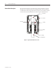
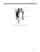
Contactor Operation e standard electrically held contactor consists of three vacuum bottles oper-
ated by an electromagnet assembly through a mechanical linkage (See Figure
1.3).
Electro-Mechanical Control (Series D)
• Whenthecontrolcircuitisenergized,currentowsthroughbothaclosingcoil
and hold-in coil, creating an electromagnet.
• iselectromagnetpullsthearmatureplatetowardsthecoilcoreswhichalso
rotates the actuator sha.
• eactuatorplate,inturn,pushestheinsulatorandmovableshaup,closing
the contacts inside the vacuum bottle.
• econtrolcircuiteconomizing/auxiliarycontacts,locatedonthelesideof
the contactor, change state once the contactor closes.
• ecurrentthatisenergizingtheclosingcoilisthenswitchedo.econtac-
tor remains closed by the hold-in coil only.
• econtactorisopenedbyde-energizingthehold-incoil.
e mechanical latch version of the contactor operates basically the same way
with the following exceptions:
• Bothcoilsarede-energizeduponclosingofthecontactor,andthearmatureis
held in the closed position by a spring-loaded latching mechanism.
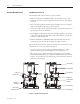
• econtactorisopenedbyenergizingatripcoilwhichpullsthelatchaway
from the armature, or by engaging a manual trip mechanism via a pushbutton
located on the front of the medium voltage door (see Figure 1.4).
Note: External control relays and a rectication circuit are used to control the
standard DC closing and hold-in coils on the contactor.