
User Manual


4-22 Maintenance
1502-UM051E-EN-P – June 2013
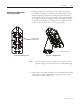
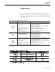
Top cartridges normally closed
(See Note on previous page)
Bottom cartridges normally open
Auxiliary assembly removed
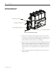
Figure 4.27 – Auxiliary Contact Assembly
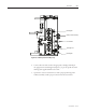
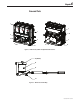
3. Positionthenewassemblyonthelesideplateofthecontactorwiththe
camfollowers(seeFigure4.28)protrudingthroughtherectangularholesin
the operating lever. Install and allow the mounting bolts to remain loose so
that the assembly can slide vertically on its mounting slots.
4. Withthecontactor“o ”,pushtheentireauxiliaryassemblyupuntilthecam
followers bottom out against the top of the rectangular holes in the operat-
ingleverasshowninFigure4.28(makesurethearmatureplateisagainst
thestopsuchthatthecontactorisfullyopen).Atthispoint,thetopsetof
auxiliarycontactsare“closed”andthebottomsetofauxiliarycontactsare
“op e n”.
5. Tightenandtorque(6-lb)themountingboltstoxthepositionofthe
auxiliaryassembly.
Auxiliary Contact Replacement
and Set-Up Procedure (cont.)