
User Manual

Maintenance 4-17
1502-UM051E-EN-P – June 2013
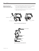
1. Makesurethecontactorisintheopen(ortripped)state.
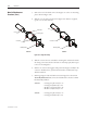
2. Removelatchpivotboltwitha3/16"AllenkeyasshowninFigure4.21,and
remove the lever assembly. e latch spring is no longer retained at this
pointandmayfalloutofthecore–donotmisplacethisspring.
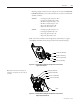
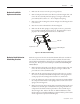
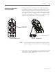
3. RemovetherollermountingboltasshowninFigure4.23allowingtheroller
to be removed.
4. Insertthenewrollerandinstalltherollermountingbolt.
5. Makesurethatthelatchspringisseatedproperlyinthecore,positionthe
lever assembly and install the latch pivot bolt. e spring must be seated
properly in the retaining holes in both the core and the lever.
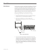
Trip Coil Lever
Roller mounting bolt
Latch roller
Figure 4.23 – Mechanical Latch Assembly
Withtheexceptionoftheroller,thelatchmechanismwilllasttheratedlifeof
the contactor. If the contactor is used beyond the rated life, the latch mecha-
nism should be refurbished by replacing the lever assembly, latch spring and the
armatureplate.esepartscanbeorderedpre-assembledasRefurbishingKit
#80158-058-51.
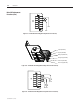
1. Removelatchpivotboltwitha3/16"AllenkeyasshowninFigure4.21,and
remove the lever assembly. e latch spring is no longer retained at this
point and can be removed and discarded.
2. Makesurethatthenewlatchspringisseatedproperlyinthecore;position
the new lever assembly and install the latch pivot bolt. e spring must be
seated properly in the retaining holes in both the core and the lever.
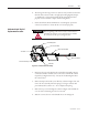
3. Loosenthelockingnutonthereturnspringcompressionboltandwithdraw
thecompressionboltuntilthereturnspringisrelaxed.Removethereturn
springasshowninFigure4.2.
4. Removethearmatureplatemountingbolts.Discardthearmatureplateand
installthenewarmatureplate.Reinstallthereturnspringandadvancethe
compressionboltuntilthearmatureplatemakescontactwiththestopas
showninFigure4.10.Advancetheboltoneadditionalfullturntoensure
thatthecontactoropensfully.Holdingthecompressionboltinpositionwitha
wrench,tightenthecompressionboltlockingnut.
Mechanical Latch Roller
Replacement Procedure
Mechanical Latch Mechanism
Refurbishing Procedure