
User Manual

Maintenance 4-15
1502-UM051E-EN-P – June 2013
8. eclosingcoilisthelargerofthetwo(SeriesDonly)andislocatedtoward
thefrontofthecontactor.Refertotheappropriatewiringdiagram(Chapter
3–Installation)toensurethatthebridgediodeand/orMOVleadsare
properly connected and for complete control wiring details.
9. Ensurethatallleads,diodesandMOVsaresecuredtightly.Operatethe
contactor several times to ensure that the core is located properly.
Beforebeginningworkonthecontactor,ensurethatitis
isolatedfromallpowersourcesandlockedout,andthat
thecontactorisintheopen(ortripped)state.
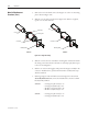
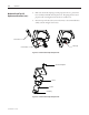
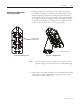
Figure 4.20 – Mechanical Latch Assembly
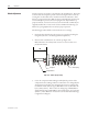
1. Disconnectthetripcoilleadsfromtheterminalblockassembly.etrip
coilleadsaretheblueandwhitewiresconnectedtoterminals"B"and"D"
respectively(seeFigure4.18or4.19).Cutanywiretiesfasteningtheleadsto
the contactor base.
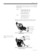
2. Removelatchpivotboltwitha3/16"AllenkeyasshowninFigure4.21,and
remove the lever assembly. e latch spring is no longer retained at this
pointandmayfalloutofthecore–donotmisplacethisspring.
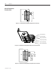
3. RemovethetripcoremountingboltasshowninFigure4.22andslidethe
core out of the coil allowing the coil to be removed.
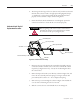
4. Slidethecoreintothenewcoilandinstallthecoremountingbolt.
Mechanical Latch Trip Coil
Replacement Procedure
A T T E N T I O N
Latch Lever Assembly
Yoke Plate
Latch Roller
Manual Trip Actuator
Manual Trip Guide Block
Trip Coil (core hidden)
Core Mounting Plate