
User Manual

4-12 Maintenance
1502-UM051E-EN-P – June 2013
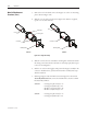
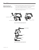
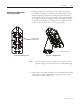
3. Removethetwoboltswhichconnectthemagnetcoretothecoremounting
plateasshowninFigure4.14.
4. SlidethecoreoutofthecoilasshowninFigure4.14.Ifthereisatightt,
tap the core out with a hammer.
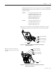
Core
Mounting Plate
Coil Leads
Series D
Hold-in Coil
Closing Coil
Core
Mounting Plate
Coil Lead
Series E
Figure 4.14 – Magnet Assembly
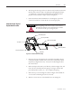
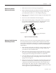
5. Slidethecoreintothenewcoilwiththemountingholeendlocatedtowards
theclosingcoil.Ensurethatthecoilleadsareorientedproperlywithrespect
to the core mounting holes.
6. Boltthecoretothemountingplateandpositionthemagnetassemblyinthe
contactor.Installthethree(3)boltswhichretaintheassemblyandtorque
allboltsto20-lb.
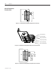
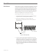
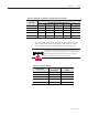
7. ReferringtoFigures4.15and4.16forSeriesDorFigure4.17forSeriesE
electrically held contactors, connect the leads from the coil to the terminal
blockassemblyasfollows:
Series D: • Closingcoil(yellowlead)to“C”
• Closingcoil(blacklead)to“D”
• Hold-incoil(yellowlead)to“P”
• Hold-incoil(bluelead)to“N”
Series E: • Closingcoil(yellowlead)to“C”
• Closingcoil(blacklead)to“N”
Main Coil Replacement
Procedure (cont.)