
User Manual

Maintenance 4-11
1502-UM051E-EN-P – June 2013
18. Operatethecontactorseveraltimestoensureproperfunction.
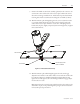
19. Wipedowntheexteriorsurfaceofeachvacuumbottlewithacleanlint-free
cloth.
20. Replacetheinterphasebarriersandretainingbrace.
21. Again,accountforalltoolsusedduringtheaboveprocedure.Ifanytoolsare
unaccounted for, do not energize the equipment.
Beforebeginningworkonthecontactor,ensurethatitis
isolatedfromallpowersourcesandlockedout.
Forthesafetyofmaintenancepersonnel,removethecontrolwiringfromthe
contactor by disconnecting the control wire plug before starting any disassembly
of the contactor.
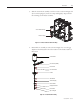
1. Disconnectthecoilleadsfromtheterminalblockassembly.eclosingand
hold-in coils are both wound on one bobbin, therefore, all four coil leads must
beremoved(theMOVsand/orbridgediodeleadsmaycomelooseaswell).
SeeFigures4.15to4.19fortheappropriateconnections.
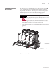
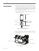
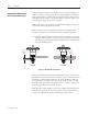
2. Removethethreeboltsfromthebottomofthemagnetassemblyandwith-
drawtheassemblyfromthecontactorasshowninFigure4.13.
Terminal block assembly
Magnet assembly
Figure 4.13 – Magnet Assembly Removed
Main Coil Replacement
Procedure
A T T E N T I O N