
User Manual

4-10 Maintenance
1502-UM051E-EN-P – June 2013
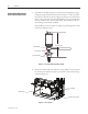
Ifthedimensionislessthan7.6mm(0.300in.),loosenthegaplockingnuton
allthree(3)bottles.StartingonphaseB,turnthegapadjustmentnutupwards
until7.6mm(0.300in.)isachieved.RepeatthisprocedureforphasesAandC,
ensuringthatthemeasurementsareequalforallthree(3)phases.Tightenand
torquethegaplockingnutsforallthree(3)phases.
Note:Ensurethatthearmatureplateissolidlypositionedagainstthestopand
compress the return spring further if necessary.
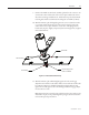
Note:Accountforalltools,includingtheset-uprod,usedduringtheabove
procedure. If any tools are unaccounted for, do not energize the equipment.
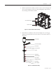
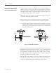
17. Usingthe“TEST”controlcircuitinthestarter,energizethecontactorand
checkforminimumallowableovertravelonallthreevacuumbottleassemblies
withafeelergauge.eovertraveldimensionshallbe2.5mm(0.100in.)mini-
mumasshowninFigure4.12.
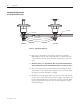
2.5 mm
(0.100 in.)
Min.
2.5 mm
(0.100 in.)
Min.
Side View
Front View
Figure 4.12 – Minimum Allowable Overtravel
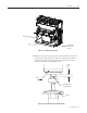
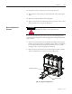
Iftheovertraveldimensionislessthan2.5mm(0.100in.),leavethecontactorener-
gizedandloosentheloadterminalnutonallthree(3)phases.Turntheinsulator
downwardsonphaseBuntilthedimensionof2.5mm(0.100in.)isachieved,
thentightentheloadterminalnut.RepeatthisprocedureforphasesAandC,
ensuringthatthemeasurementsareequalforallthree(3)phases.Tightenand
torquethegaplockingnutsonallthree(3)phases.
Note:Boththe7.6mm(0.300in.)and2.5mm(0.100in.)dimensionsmustbe
achieved for proper function. If it is not possible to achieve these dimensions,
consultyourlocalRockwellAutomationeldsupportrepresentative.
Vacuum Bottle Replacement
and Set-up Procedure (cont.)