
User Manual

4-6 Maintenance
1502-UM051E-EN-P – June 2013
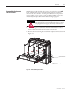
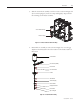
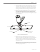
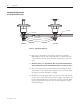
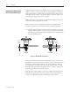
7. Reassembletheassemblyusinganewvacuumbottle,leavingthebottomgap
lockingnutandlockwashero.Positiontheinsulatortoachievethe243.3
mm(9.58in.)dimensionasshowninFigure4.6andleavetheloadterminal
nutloose(thepositionoftheloadterminalshallbeintheoppositedirection
ofthewearindicatorlineonthemovablesha).Repeatthisprocedurefor
the remaining vacuum bottle assemblies.
e9.58"dimensionisnotcritical,itissimplyagoodstartingpointinorder
tomaketheinstallationeasier.
Movable Shaft
Load Terminal
Load Terminal Nut
9.58” (243.3 mm)
Figure 4.6 – Reassembled Vacuum Bottle Assembly
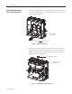
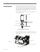
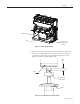
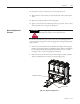
8. Positiona4.76mm(0.1875in.)diameterrod,e.g.drillbitorscrew,between
thearmatureplateandtheyokeplatetopreventthecontactorfromclosing
asshowninFigure4.7.
Yoke Plate
(Position 3/16” rod here)
Armature Plate
Figure 4.7 – Set-up Position
Vacuum Bottle Replacement
and Set-up Procedure (cont.)