
User Manual

Installation
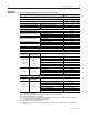
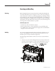
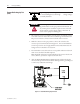
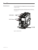
Mounting e Allen-Bradley vacuum contactor is normally xed mounted (bolted down) in
the enclosure of the controller. ere are four (4) mounting holes at the base of
the contactor (Figure 3.1) to secure it to the enclosure. For reversing, autotrans-
former and 2-speed controllers, one contactor may be mounted on top of the
other. ere are four (4) threaded mounting holes at the top of the contactor to
accommodate this conguration.
IMPORTANT: e contactor is a bolted assembly and is therefore subject to twisting if fastened to an uneven surface.
e contactor mounting plate has small stand-os that permit the contactor to be fastened without twisting the frame.
e contactor may not function correctly if it is forced onto an uneven mounting surface.
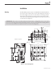
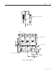
97,2 [3.83]
13,49 [0.531]
19,1 [0.75]
38,1 [1.50] (Typical Terminal Detail)
19,1 [0.75]
31,8 [1.25]
152,4 [6.00]
(Mounting Hole Centers)
12,7 [0.50]
41,3 [1.63]
127
[5.00]
462,5
[18.21]
437,1 [17.21]
457.2 [18.00] (Mounting Hole Centers)
127
[5.00]
104,2
[4.10]
32,4
[1.27]
14.27 [0.562]
(4) Mounting Holes
17,5 [0.69]
194,1 [7.64]
260,7 [10.27]
324,2 [12.77]
270 [10.63]
194,1 [7.64]
158,2�
[6.23]
267,31�
[10.52]
438,7�
[17.27]
16,7
[0.66]
Dimensions = mm [inches]
Figure 3.1 – Contactor Mounting Details
Chapter 3
1502-UM051E-EN-P – June 2013