Medium Voltage Contactor 800A, 2400-7200 V Bulletin 1502 (Series D and E) User Manual
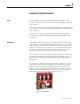
Important User Information Read this document and the documents listed in the Additional Resources section about installation, configuration, and operation of this equipment before you install, configure, operate, or maintain this product. Users are required to familiarize themselves with installation and wiring instructions in addition to requirements of all applicable codes, laws, and standards.
Table of Contents Chapter 1 Contactor Product Description Scope .............................................................................................................................. 1-1 Description .................................................................................................................... 1-1 Vacuum Bottle Description ........................................................................................1-2 Contactor Operation Electro-Mechanical Control (Series D) ..
ii Table of Contents – 800 A Medium Voltage Contactor User Manual Chapter 4 Maintenance Tool Requirements ...................................................................................................... 4-1 Recommended Torque Values ................................................................................... 4-1 Routine Maintenance .................................................................................................. 4-1 Vacuum Bottle Replacement and Set-up Procedure ............
Chapter 1 Contactor Product Description Scope This User Manual pertains to Allen-Bradley's Bulletin 1502, 800A vacuum contactors. It applies to both Series D and E versions of the Bulletin 1502 (800 Amp) contactors. Series D vacuum contactors are intended for use with electro-mechanical (relay) control circuits. They may not be used with IntelliVAC and IntelliVAC Plus control modules.
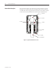
1-2 Contactor Product Description Vacuum Bottle Description The vacuum bottle (Figure 1.2) consists of two contacts enclosed in a ceramic housing. One contact is mounted on a fixed shaft, and the other is attached to a movable shaft. The bearing and stainless steel bellows ensure that the movable contact tracks accurately and maintains vacuum integrity within the bottle. Fixed shaft Ceramic Arc shield Contacts Bellows Bearing Movable shaft 1502-UM051E-EN-P – June 2013 Figure 1.
Contactor Product Description Contactor Operation 1-3 The standard electrically held contactor consists of three vacuum bottles operated by an electromagnet assembly through a mechanical linkage (See Figure 1.3). Electro-Mechanical Control (Series D) • When the control circuit is energized, current flows through both a closing coil and hold-in coil, creating an electromagnet. • This electromagnet pulls the armature plate towards the coil cores which also rotates the actuator shaft.
1-4 Contactor Product Description Contactor Operation (cont.) IntelliVAC Control (Series E) The electrically held vacuum contactor operates as follows: • When the IntelliVAC and IntelliVAC Plus control modules receive a close command, the contactor coil is energized, the current creates an electromagnet in the coil. • The electromagnet pulls the armature plate towards the coil core, rotating the shaft and causing the actuator plate to move upwards.
Contactor Product Description Latch Lever 1-5 Latch Spring Mechanical Latch Trip Coil Manual Trip Mechanism Contactor Closed Figure 1.
1-6 Contactor Product Description Contactor Identification Each contactor is identified with a nameplate (Figure 1.5) attached to the interphase barrier retainer at the front of the contactor. The nameplate information includes the Catalog Number, Series Letter, Voltage Rating, Non-enclosed Current Rating, Interrupting Capacity, Altitude Range, CSA and UL markings. VACUUM CONTACTOR CONTACTEUR SOUS VIDE CAT. 2500- IEC60470 C US E102991 LR12235 MADE IN CANADA Catalog No.
Contactor Product Description Contactor Specifications 1-7 Table 1.B - Bulletin 1502 Medium Voltage 800 Amp Contactor Ratings Description Voltage Ratings Maximum Rated Voltage System Voltages Dielectric Voltage Withstand Rating Basic Impulse Level (B.I.L.
1-8 Contactor Product Description Contactor Specifications (cont.) Table 1.B - Bulletin 1502 Medium Voltage 800 Amp Contactor Ratings (cont.
Chapter 2 Receiving and Handling Receiving Before leaving the factory, the contactors have been tested both mechanically and electrically. Immediately upon receiving the contactor, remove the packing material and check the contactor for possible shipping damage. If damage is found, do not discard any of the packaging material and, if possible, note the damage on the Bill of Lading before accepting receipt of the shipment. Report any damage immediately to the claims office of the common carrier.
2-2 Receiving and Handling Handling (cont.) 2. Select or adjust the rigging lengths to compensate for an unequal weight distribution of the load and maintain the contactor in an upright position at all times. 3. To reduce the tension of the rigging and the compressive load on the lifting device, do not allow the angle between the lifting cables and vertical to exceed 45 degrees. 4. Never lift a contactor above an area where personnel are located.
Receiving and Handling Vacuum Bottle Integrity Test 2-3 The internal dielectric condition and vacuum integrity of the vacuum bottles is determined by this test. Clean the outside of the vacuum bottles with a nonlinting cloth or industrial type wiper before performing the test. Test each bottle individually during this test. S H O C K H A Z A R D X-ray emissions may be produced if a voltage higher than 25,000 Volts is applied across the open contacts of a vacuum bottle.
2-4 Receiving and Handling Vacuum Bottle Integrity Test S H O C K H A Z A R D High-voltage is present during this test. (cont.) be exercised during this test since high potentially hazardous. Caution should voltage testing is ATTENTION Before doing any work on the contactor, the controller isolating switch must be in the open position and locked out. If any control power is used from a separate source, it should also be isolated.
Receiving and Handling 2-5 The allowable leakage current of 5 mA is a maximum for new dry equipment, and is exclusive of leakage due to test equipment leads. The test setup leakage can be determined by running the dielectric test with test leads not connected to the contactor and noting the maximum leakage current. If this value is more than 2 milliamperes, it should be added to the 5 mA limit when testing the vacuum bottles.
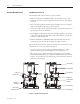
Chapter 3 Installation Mounting The Allen-Bradley vacuum contactor is normally fixed mounted (bolted down) in the enclosure of the controller. There are four (4) mounting holes at the base of the contactor (Figure 3.1) to secure it to the enclosure. For reversing, autotransformer and 2-speed controllers, one contactor may be mounted on top of the other. There are four (4) threaded mounting holes at the top of the contactor to accommodate this configuration.
3-2 Installation Electrical Connections The control wiring from the low voltage panel to the contactor is made through a wire harness and connects to the left side of the contactor with a male and female configured wire plug. The power wiring terminates on the rear side of the contactor to the line and load terminals. Holes are provided to accommodate 12 mm (1/2 in.) size hardware (Figure 3.2). Figure 3.
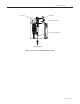
Installation 3-3 Mechanical Latch Assembly Rating Label Housing Assembly Lifting Hazard Label Terminal Block Assembly Shaft Assembly Contactor Mounting Hole Figure 3.
3-4 Installation Wiring and Schematic Diagrams Figure 3.
Installation 3-5 WIRING DIAGRAM 800A VACUUM CONTACTOR AUXILIARY CONTACTS A B I J K L YELLOW BLUE C COIL MOV YELLOW BLACK D P E F G H MOV N A B C D E F G H I J K L M N P A, B, C, D, E, F, G, H, I - SOCKETS J, K, L, M, N, P - PINS SCHEMATIC 800A VACUUM CONTACTOR AUXILIARY CONTACTS M A B M F E M H G M J I M K L MOV C CC D MOV N HC P M CC - CLOSING COIL HC - HOLD-IN COIL 80113-646-28 Figure 3.
3-6 Installation Figure 3.
Installation 3-7 Figure 3.
3-8 Installation Figure 3.
Installation 3-9 Typical Electrical Diagrams Figure 3.
3-10 Installation Figure 3.
Installation 3-11 Figure 3.
1502-UM051E-EN-P – June 2013 Figure 3.12 – Typical Wiring and Schematic Diagram for 800 amp FVNR Controller (Series E • Mechanical Latch Contactor) 1 1 ISb 30 1A F3 4.0A 8 2400V-6900V,3Ø, 50/60Hz L1 L2 L3 GRD 9 E X F J M (8) (5) M OL OL 2.
Chapter 4 Maintenance Tool Requirements When maintenance is performed on the vacuum contactor, one or all of the following tools may be required. • • • • • • • • • • Recommended Torque Values 3/8" drive ratchet wrench with extension 3/8" drive torque wrench Standard 3/8" drive sockets; 7/16", 9/16", 3/4" Open end wrenches: 7/16", 9/16", 11/16", 3/4", 7/8" 3/16" Allen key 3/16" dia. rod Slot head screwdrivers; 1/8" wide, 1/4" wide Feeler gauge set (0.125" and 0.
4-2 Maintenance Routine Maintenance (cont.) Main Contact Inspection • Visually inspect the wear of the main contacts with the contactor energized. When any part of the wear indicator line, located on the front side of the hex shaft, moves up into the bearing, replace all three vacuum bottles. (Refer to Figure 4.11) Under normal conditions, this will not be necessary until the contactor has gone beyond the 250,000 rated life (100,000 for mechanical latch contactors).
Maintenance Vacuum Bottle Replacement Set-Up Procedure 4-3 The following procedure shall be used to remove and replace the vacuum and bottles. This procedure can be performed with the contactor remaining in the power cell of the controller. After this procedure has been completed, the contactor will be set up to operate properly at 1000 m (3300 ft). Refer to the Altitude Adjustment procedure for other altitude setting on page 4-18.
4-4 Maintenance Vacuum Bottle Replacement and Set-up Procedure (cont.) 3. Loosen the locking nut on the return spring compression bolt and withdraw the compression bolt until the return spring is relaxed. Remove the return spring as shown in Figure 4.2. Compression Bolt and Locking Nut Return Spring Figure 4.2 – Removal of Return Spring 4. Remove the bolts which retain the load terminals at the rear of the contactor and the main mounting bolt at the top of one vacuum bottle as shown in Figure 4.
Maintenance 4-5 5. Slide the vacuum bottle assembly out of the contactor as shown in Figure 4.4 (the overtravel spring may need to be compressed slightly). Repeat this for the remaining vacuum bottle assemblies. Vacuum Bottle Assembly Overtravel Spring Figure 4.4 – Removal of Vacuum Bottle Assembly 6. Disassemble one assembly at a time as shown in Figure 4.5. Leave the gap adjustment nut directly below the rocker washer on the insulator stud near the bottom.
4-6 Maintenance Vacuum Bottle Replacement and Set-up Procedure (cont.) 7. Reassemble the assembly using a new vacuum bottle, leaving the bottom gap locking nut and lock washer off. Position the insulator to achieve the 243.3 mm (9.58 in.) dimension as shown in Figure 4.6 and leave the load terminal nut loose (the position of the load terminal shall be in the opposite direction of the wear indicator line on the movable shaft). Repeat this procedure for the remaining vacuum bottle assemblies. The 9.
Maintenance 4-7 9. Position the middle vacuum bottle assembly (phase B) in the contactor. Ensure that the rocker washer is below the actuator plate and that the wear indicator line is facing towards the front. Install and torque the load terminal retaining bolt and the vacuum bottle mounting bolt to 20 ft•lb (27 N•m). 10.
4-8 Maintenance Vacuum Bottle Replacement and Set-up Procedure (cont.) Rocker Bar Rocker Bar Rocker Washer Gap Adjustment Nut Side View Gap Locking Nut Front View Figure 4.9 – Rocker Washer Adjustment 12. Repeat steps 9, 10 and 11 for the remaining vacuum bottle assemblies. Note: Make sure that the rocker washers for all three assemblies just make contact with the rocker bars as this will ensure synchronized contact movement. 13.
Maintenance 4-9 Armature plate Stop Armature plate makes contact with Stop Figure 4.10 – Return Spring Installation 16. With the contactor in the open position, measure the distance between the bottom of the bearing and the top of the wear indicator line on all three vacuum bottles with a feeler gauge. This dimension shall be 7.6 mm (0.300 in.) minimum as shown in Figure 4.11. 7.6 mm (0.30 in.) Min. Vacuum Bottle Wear indicator line on operating shaft Insulator Figure 4.
4-10 Maintenance Vacuum Bottle Replacement and Set-up Procedure (cont.) If the dimension is less than 7.6 mm (0.300 in.), loosen the gap locking nut on all three (3) bottles. Starting on phase B, turn the gap adjustment nut upwards until 7.6 mm (0.300 in.) is achieved. Repeat this procedure for phases A and C, ensuring that the measurements are equal for all three (3) phases. Tighten and torque the gap locking nuts for all three (3) phases.
Maintenance 4-11 18. Operate the contactor several times to ensure proper function. 19. Wipe down the exterior surface of each vacuum bottle with a clean lint-free cloth. 20. Replace the interphase barriers and retaining brace. 21. Again, account for all tools used during the above procedure. If any tools are unaccounted for, do not energize the equipment.
4-12 Maintenance Main Coil Replacement Procedure (cont.) 3. Remove the two bolts which connect the magnet core to the core mounting plate as shown in Figure 4.14. 4. Slide the core out of the coil as shown in Figure 4.14. If there is a tight fit, tap the core out with a hammer. Hold-in Coil Core Core Closing Coil Coil Lead Coil Leads Mounting Plate Mounting Plate Series E Series D Figure 4.14 – Magnet Assembly 5.
Maintenance 4-13 Referring to Figure 4.18 for Series D or Figure 4.
4-14 Maintenance Main Coil Replacement Procedure (cont.) Yellow Black Figure 4.17 – Terminal Block Assembly (Electrically Held Series E Contactor) Trip Coil (blue lead) Trip Coil (white lead) Closing Coil (black lead) Closing Coil (yellow lead) Hold-in Coil (blue lead) Hold-in Coil (yellow lead) Figure 4.18 – Terminal Block Assembly (Mechanically Latched Series D Contactor) B White A C Blue D Black Yellow Trip Coil Main Coil Figure 4.
Maintenance 4-15 8. The closing coil is the larger of the two (Series D only) and is located toward the front of the contactor. Refer to the appropriate wiring diagram (Chapter 3 – Installation) to ensure that the bridge diode and/or MOV leads are properly connected and for complete control wiring details. 9. Ensure that all leads, diodes and MOVs are secured tightly. Operate the contactor several times to ensure that the core is located properly.
4-16 Maintenance Mechanical Latch Trip Coil Replacement Procedure (cont.) 5. Make sure that the latch spring is seated properly in the core, position the lever assembly and install the latch pivot bolt. The spring must be seated properly in the retaining holes in both the core and the lever. 6. Route the trip coil leads as they were and connect to the terminal block assembly as shown in Figure 4.18 or 4.19. Latch Pivot Bolt Latch Spring Lever Assembly Figure 4.
Maintenance Mechanical Latch Roller Replacement Procedure 4-17 1. Make sure the contactor is in the open (or tripped) state. 2. Remove latch pivot bolt with a 3/16" Allen key as shown in Figure 4.21, and remove the lever assembly. The latch spring is no longer retained at this point and may fall out of the core – do not misplace this spring. 3. Remove the roller mounting bolt as shown in Figure 4.23 allowing the roller to be removed. 4. Insert the new roller and install the roller mounting bolt. 5.
4-18 Maintenance Altitude Adjustment Vacuum contactors are sensitive to the altitude at the installation site. This is due to the fact that the atmospheric pressure assists in closing the main contacts by exerting force on the bellows at the movable end of the vacuum bottles. Since this force is proportional to the difference between internal bottle pressure and external atmospheric pressure, the return spring must be adjusted for the appropriate altitudes.
4-19 Maintenance Table 4.A – Dimension “A” Settings in Inches (millimeters in brackets) EXISTING ALTITUDE RANGE NEW ALTITUDE RANGE Increase or Decrease Dimension “A” by: 1000-2000 m 2000-3000 m 3000-4000 m 0-1000 m 4000-5000 m 0-1000 m N/A +0.073 (1.85) +0.140 (3.56) +0.194 (4.93) +0.246 (6.25) 1000-2000 m -0.073 (-1.85) N/A +0.067 (1.70) +0.121 (3.07) +0.173 (4.39) 2000-3000 m -0.140 (-3.56) -0.067 (-1.70) N/A +0.054 (1.37) +0.106 (2.69) 3000-4000 m -0.194 (-4.93) -0.121 (-3.
4-20 Maintenance Drop-out Time Conversion Series D The average normal drop-out time for the contactor is 200 ms. The "fast dropout" contactor has a drop-out time less than 60 ms. Conversion from "normal" to "fast" or vice-versa is easily achieved by changing the control component wired in parallel with the closing coil (see Figures 3.3 and 3.4). The required components can be ordered from Rockwell Automation and installed per the appropriate schematic.
Maintenance Auxiliary Contact Replacement and Set-Up Procedure 4-21 1. If replacing a single contact cartridge, remove the appropriate leads and turn the plastic retaining screws to allow removal of the cartridge as shown in Figures 4.25 and 4.26. Insert the new cartridge and position the retaining screws to hold it in place. Reconnect the leads to the cartridge.
4-22 Maintenance Auxiliary Contact Replacement and Set-Up Procedure (cont.) (See Note on previous page) Top cartridges normally closed Bottom cartridges normally open Auxiliary assembly removed Figure 4.27 – Auxiliary Contact Assembly 3. Position the new assembly on the left side plate of the contactor with the cam followers (see Figure 4.28) protruding through the rectangular holes in the operating lever.
Maintenance 4-23 Mounting Bolt Auxiliary Contact Assembly Cam Followers Operating Lever Mounting Bolt Figure 4.28 – Auxiliary Contact Assembly Set-up 6. Connect all control wire leads to the appropriate cartridge terminals per the appropriate electrical diagram (Chapter 3), or per the specific electrical drawing “ED” supplied with the starter unit. 7. Operate the contactor several times to ensure proper positioning of the auxiliary assembly as well as proper connection of the control wires.
4-24 Maintenance 1502-UM051E-EN-P – June 2013
Chapter 5 Troubleshooting If an operating problem occurs, use the following troubleshooting chart to isolate the cause of the failure and find the corrective action. If the corrective action fails to resolve the problem, consult your local Rockwell Automation field support representative. Table 5.
5-2 Troubleshooting 1502-UM051E-EN-P – June 2013
Chapter 6 Renewal Parts 1 3 7 14 5 6 8 2 12 4 9 10 Figure 6.1 – Bulletin 1502, 800A Electrically Held Vacuum Contactor 20 (hidden) 18 19 21 Figure 6.
6-2 Renewal Parts Table 6.
Medium Voltage Products, 135 Dundas Street, Cambridge, ON, N1R 5X1 Canada, Tel: (1) 519.740.4100, Fax: (1) 519.623.8930, www.ab.com/mvb Publication 1502-UM051E-EN-P – June 2013 Supersedes Publication 1502-UM051D-EN-P – December 2009 Copyright © 2013 Rockwell Automation, Inc. All rights reserved. Printed in Canada.