
User Manual

50 Rockwell Automation Publication 1502-UM052H-EN-P - June 2013
Chapter 4 Maintenance
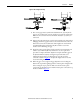
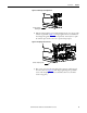
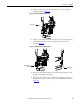
Figure 44 - Removal of Mechanical Trip Mechanism
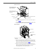
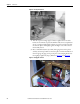
6. Remove the “E” clip and washer from the latch lever assembly shaft and
then remove the shaft (Figure 45
). Remove the latch lever assembly from
the mechanical latch base. Note that the return spring is “seated” on the
right side of the mechanical latch base. (Note: Contactor not shown for
clarity).
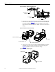
Figure 45 - Removal of Latch Lever Assembly
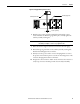
7. Using a 5/16” socket, remove the #10-32 hardware holding the stainless
steel guide/stop plate in place, and then remove the guide/stop plate
(Figure 46
). (Note: Contactor not shown for clarity).
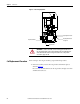
Figure 46 - Removal of Guide/Stop Plate
Mechanical Trip
Mechanism
¼-20 Hardware
(Qty 2)
Contactor
Return Spring Seat
Shaft
“E” Clip and Washer
Latch Lever Assembly
Guide/Stop Plate
#10-32 Hardware