User Manual Medium Voltage 400A Contactor - Series E Publication Number 1502-UM052H-EN-P
Important User Information Read this document and the documents listed in the Additional Resources section about installation, configuration, and operation of this equipment before you install, configure, operate, or maintain this product. Users are required to familiarize themselves with installation and wiring instructions in addition to requirements of all applicable codes, laws, and standards.
Table of Contents Chapter 1 Product Description Contactor Description . . . . . . . . . . . . . . . . . . . . . . . . . . . . . . . . . . . . . . . . . . . . . 5 Vacuum Bottle Description . . . . . . . . . . . . . . . . . . . . . . . . . . . . . . . . . . . . . . . . . 6 Standard Electrically Held Contactor Operation . . . . . . . . . . . . . . . . . . . . . 6 Mechanically Latched Contactor Operation. . . . . . . . . . . . . . . . . . . . . . . . . . 7 IntelliVAC and IntelliVAC Plus Control . . . . . . .
Table of Contents Chapter 5 Troubleshooting Troubleshooting and Contactor Coil Resistance . . . . . . . . . . . . . . . . . . . . 55 Chapter 6 Spare Parts 4 Bulletin 1502 Spare Parts Diagrams and Chart. . . . . . . . . . . . . . . . . . . . . .
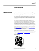
Chapter 1 Product Description Contactor Description The Allen-Bradley, Bulletin 1502, 400 A vacuum contactors are designed for applications in the 2400 and 7200V range. The contactor is suitable for all types of AC loads, for example: three-phase motors, transformers, power capacitors and resistive heating loads. The contactor uses three interrupters (hereafter referred to as vacuum bottles) operated by an electromagnet assembly through a mechanical linkage.
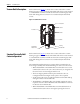
Chapter 1 Product Description Vacuum Bottle Description Each vacuum bottle (Figure 2) consists of two contacts enclosed in a ceramic housing: an upper contact mounted to a fixed shaft, and a lower contact mounted to a movable shaft. A stainless steel bellows ensures the vacuum integrity of the bottle while letting the lower contact move towards and away from the fixed contact.
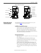
Product Description Chapter 1 Figure 3 - Vacuum Contactor Operation C.P.T.
Chapter 1 Product Description • The contactor can be opened electrically by energizing a trip coil which pulls the latch away from the armature, or by a push button mounted on the power cell door that mechanically releases the contactor. Note: The standard mechanical latch contactor requires external 120V AC (or DC) control relays and rectification circuit to control the standard DC closing and trip coils on the contactor (when IntelliVAC or IntelliVAC Plus is not used).
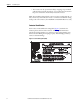
Product Description Chapter 1 The following catalog number explanation is used to identify the contactor and should be used when contacting your local Rockwell Automation Sales office, or the factory, for assistance.
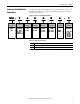
Chapter 1 Product Description Contactor Specifications Table 2 - Bulletin 1502 Medium Voltage 400 Amp Contactor Ratings Voltage Ratings(1) Maximum Rated Voltage 7200 System Voltages 2400, 3300, 4160 4800, 6600, 6900 Dielectric Voltage Withstand Rating For 60 seconds (kV) 18.2 / 20 (IEC) Basic Impulse Level (B.I.L.
Product Description Chapter 1 Table 2 - Bulletin 1502 Medium Voltage 400 Amp Contactor Ratings (Continued) Operational Characteristics Mechanical Life (Operations) x 1000 (4) Electrically Held 2500 Mechanical Latch 100 Electrical Life (Operations) x 1000(4) 1000 Switching Frequency (Operations per hour) Electrically Held 600 Mechanical Latch 150 Opening and Closing Times Electro-Mechanical (Relay) Control (Mechanical Latch Only) Maximum Closing Time (120 VAC) 50 or 60 Hz (milliseconds) 160
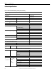
Chapter 1 Product Description Table 3 - Altitude Derating Altitude Rating Reduce Max. Continuous Current Rating By: Reduce B.I.L. Withstand Rating by: 400 A 800 A 0...1000 m (0...3300 ft) – – – 1001...2000 m (3301...6600 ft) 10 A 20 A 6.0 kV 2001...3000 m (6601...9900 ft) 20 A 40 A 12.0 kV 3001...4000 m (9901...13,200 ft) 30 A 60 A 18.0 kV 4001...5000 m (13,201...16,500 ft) 40 A 80 A 24.0 kV Product Approvals 12 • • • • UL347 CSA22.2 No. 14 and T.I.L.
Chapter 2 Receiving and Handling Receiving The contactors have been tested both mechanically and electrically before leaving the factory. Immediately upon receiving the contactor, remove the packing material and check the contactor for possible shipping damage. If damage is found, do not discard any of the packaging material and, if possible note the damage on the “Bill of Lading” before accepting the shipment. Report any damage immediately to the claims office of the common carrier.
Chapter 2 Receiving and Handling Pre-Energization Inspection Before placing the contactor in service, inspect it carefully for possible damage sustained in transit or maintenance: • Check housing for any cracks or breaks due to impact. • Push on the armature plate and rotating shaft to ensure mechanism is in good working order. • Inspect the contactor for dirt, stray or loose hardware, tools or metal chips. Vacuum clean if necessary.
Receiving and Handling Chapter 2 1. Clean the outside of the vacuum bottles with a non-linting cloth or industrial wipe before performing the test. 2. The contactor may be tested while it is in the power cell. The line connection of the contactor must be disconnected and the ground lead from the Hi-pot tester must be connected to the load side of the contactor. Any fuses in the top of the contactor must be removed. 3.
Chapter 2 Receiving and Handling Note: Rockwell Automation does not recommend DC Hi-pot testing because the values obtained during the test may not be a reliable indication of vacuum bottle integrity. Some specific DC “GO-NO GO” testers may provide suitable “defective” readings. DC Hi-pot testing is unreliable because of a phenomenon known as Cathode Ray Tube Effect. This occurs when one contact of the vacuum bottle has a deformity, such as a burr or deposit, while the other contact remains flat and true.
Chapter 3 Installation The electrically held and the mechanically latched contactors are fixed mounted (bolted down) in the controller’s cabinet. Two retaining tabs at the rear of the contactor’s molded base can be used for mounting. The two mounting slots at the front of the contactor’s molded base are used to secure the contactor with 1/4 in. bolts. The appropriate mounting configuration is provided inside the power cells of Allen-Bradley controllers.
Chapter 3 Installation Figure 8 - Mechanical Latch Dimensions (Optional) 1.53 2.93 Electrical Connections A wire harness connects the control wiring to the contactor from the low voltage control panel. The harness connects to a wire plug on the lower left side of the contactor. If the contactor is supplied as an OEM component for installation in a custom application, the following two control options and a connecting wire harness are available from Rockwell Automation.
Installation Chapter 3 Figure 9 - Electrical Connections (Rear View) Control Circuit Transformer Primary Fuse Clips Line Side Terminals Control Wire Plug Load Side Terminals Rockwell Automation Publication 1502-UM052H-EN-P - June 2013 19
Chapter 3 Installation Wiring and Schematic Diagrams 20 Figure 10 - Wiring Diagram - Electrically Held Contactor (for use with IntelliVAC and IntelliVAC Plus control modules only) Rockwell Automation Publication 1502-UM052H-EN-P - June 2013
Installation Chapter 3 Figure 11 - Wiring Diagram - Mechanical Latch Contactor (for use with IntelliVAC and IntelliVAC Plus control modules only) Rockwell Automation Publication 1502-UM052H-EN-P - June 2013 21
Chapter 3 Installation Figure 12 - Wiring Diagram - Mechanical Latch Contactor (for use with Electro-mechanical Control Panel Only) 22 Rockwell Automation Publication 1502-UM052H-EN-P - June 2013
Installation Chapter 3 Figure 13 - Wiring Diagram - Electrically Held Contactor, 120V AC (Normal Drop-out Time) Rockwell Automation Publication 1502-UM052H-EN-P - June 2013 23
Chapter 3 Installation Figure 14 - Wiring Diagram - Electrically Held Contactor, 230V AC (Normal Drop-out Time) 24 Rockwell Automation Publication 1502-UM052H-EN-P - June 2013
Installation Chapter 3 Figure 15 - Wiring Diagram - Electrically Held Contactor, 120V AC (Fast Drop-out Time) Rockwell Automation Publication 1502-UM052H-EN-P - June 2013 25
Chapter 3 Installation Figure 16 - Wiring Diagram - Electrically Held Contactor, 230V AC (Fast Drop-out Time) 26 Rockwell Automation Publication 1502-UM052H-EN-P - June 2013
Installation Chapter 3 Figure 17 - Wiring Diagram - Mechanically Latched Contactor (120V AC) Rockwell Automation Publication 1502-UM052H-EN-P - June 2013 27
Chapter 3 Installation Figure 18 - Typical Electrical Diagram for 400 A Full-voltage Non-reversing (FVNR) Controller with Electrically Held Contactor, 120V AC (Normal Drop-out Time) 28 Rockwell Automation Publication 1502-UM052H-EN-P - June 2013
Installation Chapter 3 Figure 19 - Typical Electrical Diagram for 400 A Full-voltage Non-reversing (FVNR) Controller with Mechanically Latched Contactor, 120V AC Rockwell Automation Publication 1502-UM052H-EN-P - June 2013 29
Rockwell Automation Publication 1502-UM052H-EN-P - June 2013 M CT1 GRD L3 L2 L1 T1 CT2 T2 CT3 T3 47 46 44 42 CPT 500VA OL OVERLOAD CURRENT LIMITING PRIMARY FUSES H2 H1 CURRENT LIMITING POWER FUSES DOOR INTERLOCK ISOLATING SWITCH GRD BUS 49 X2 X1 5 2400V-6900V 3Ø, 50/60Hz POWER BUS ISa 7 6 32 X (5) G 1 1 1 34 30 4.0A I M H 33 36 K M L M J F ISb 2.
Rockwell Automation Publication 1502-UM052H-EN-P - June 2013 1 1 1 ISb 34 30 14 14 F3 4.0A 8 (8) (5) M J I F M (7) (6) E 1A 1A 9 X 10 35 31 OL 2.
Rockwell Automation Publication 1502-UM052H-EN-P - June 2013 M CT1 GRD L3 L2 L1 T1 CT2 T2 CT3 T3 47 46 44 42 MANUAL TRIP OL OVERLOAD 49 X2 H2 CURRENT LIMITING PRIMARY FUSES X1 CPT 500VA H1 CURRENT LIMITING POWER FUSES DOOR INTERLOCK ISOLATING SWITCH GRD BUS 5 2400V-6900V 3Ø, 50/60Hz POWER BUS ISa 7 6 X (5) (6) 1 1 1 G M M 2.0A ISb L H 14 9 33 37 34 J N M P M 34A 35 EXTRA AUXILIARY CONTACT E M F 30 31 32 1A 4.
Rockwell Automation Publication 1502-UM052H-EN-P - June 2013 M CT1 GRD L3 L2 L1 T1 CT2 T2 CT3 T3 47 46 44 42 MANUAL TRIP OL OVERLOAD 49 X2 H2 CURRENT LIMITING PRIMARY FUSES X1 CPT 500VA H1 CURRENT LIMITING POWER FUSES DOOR INTERLOCK ISOLATING SWITCH GRD BUS 5 2400V-6900V 3Ø, 50/60Hz POWER BUS ISa 7 6 X (5) (6) 1 1 1 G M M 2.0A ISb L H 14 9 37 33 34 J N M P M 34A 35 EXTRA AUXILIARY CONTACT E M F 30 31 32 1A 4.
Rockwell Automation Publication 1502-UM052H-EN-P - June 2013 M CT1 GRD L3 L2 L1 T1 CT2 T2 CT3 T3 47 46 44 42 MANUAL TRIP OL OVERLOAD 49 X2 H2 CURRENT LIMITING PRIMARY FUSES X1 CPT 500VA H1 CURRENT LIMITING POWER FUSES DOOR INTERLOCK ISOLATING SWITCH GRD BUS 5 2400V-6900V 3Ø, 50/60Hz POWER BUS ISa 7 6 34 N X (5) 1 1 32 30 2.
Chapter 4 Maintenance Tool Requirements IMPORTANT Some components of this product incorporate Imperial hardware. Rockwell Automation recommends the use of the appropriate tools to successfully complete the maintenance procedure on these components. If you cannot obtain such tools, contact your area Rockwell Automation sales office for assistance. When maintenance is performed on the vacuum contactor, the following tools may be required: • 3/8-in. drive ratchet wrench with extension • 3/8-in.
Chapter 4 Maintenance Routine Maintenance ATTENTION: Before performing any maintenance on the contactor, refer to the User Manual of the starter configuration in which the contactor is installed for all service instructions and procedures. Failure to do so may result in injury to personnel or damage to the controller or contactor. ATTENTION: To avoid shock hazards, lock out incoming power and disconnect the control plug from the contactor before working on the unit.
Maintenance Chapter 4 Main Contact Inspection Visually inspect the wear of the main contacts with the contactor energized. When any part of the wear indicator line, located on the front side of the shaft, moves up into the bearing, replace all three vacuum bottles (Figure 25). Figure 25 - Vacuum Bottle Wear Indicator Vacuum Bottle Wear indicator line on operating shaft HiPot test Check the vacuum bottle integrity (see page 14). Check the insulation resistance. Lubrication Using Aeroshell No.
Chapter 4 Maintenance Figure 26 - Grease Locations Insulator Grease Grease Actuator Plates IMPORTANT Vacuum Bottle Replacement and Set-Up Procedure Do not grease the armature shaft plastic bearings. These bearings are selflubricating and do not require grease. Under normal conditions, vacuum bottles will last at least 1,000,000 operations; however, all three bottles must be replaced if any wear indicator line reaches the bearing (regardless of the number of operations).
Maintenance Chapter 4 Figure 27 - Mounting and Retaining Bolt Removal Vacuum Bottle Mounting Bolt Load Terminal Retaining Bolt and Hardware 4. Loosen the load terminal nut on one bottle assembly, tilt the bottle forward (out of the contactor) and unscrew it from the insulator stud as shown in Figure 28. Repeat this for the two remaining bottles. The load terminals, insulators and overtravel spring assemblies remain in the contactor as shown in Figure 28.
Chapter 4 Maintenance Figure 29 - Establishing Contact Gap 0.190 in. [4.82 mm] Vacuum Bottles Insulator 6. Install the load terminal retaining bolts at the rear of the contactor. Leave the load terminal nuts loose for fine adjustment of the overtravel and contact gap. Install the vacuum bottle mounting bolts at the top of the contactor (reverse of step 2). Take care to ensure the threads are aligned as cross-threading can occur.
Maintenance Chapter 4 Figure 31 - Measuring Contact Gap A1 A2 9. The contact gaps must be synchronized within 0.02 in. (0.5 mm). If the gaps are not synchronized, rotate the insulators as required to achieve this. Make sure the overtravel remains a minimum of 0.065 in. (1.65 mm) on each bottle. 10. Tighten the load terminal nut on each bottle assembly. To do this without damaging the bellows, apply wrenches to the load terminal nut and to the flattened section of the movable bottle shaft.
Chapter 4 Maintenance Figure 32 - Contact Gap Adjustment Gap Adjustment Screw Gap Adjustment Screw Locking Nut Stop Bracket Bolts Stop Bracket ATTENTION: To avoid shock hazards, lock out incoming power and disconnect the control plug from the contactor before working on the unit. Verify with a hot stick or meter that all circuits are voltage free. Failure to do so may result in severe burns, injury or death.
Maintenance Chapter 4 Figure 33 - Access to Coils Grade 5 (5/16 Hardware) to mount return spring actuator plate. Refer to page 4-1 for torque values. Grade 5 (5/16 Hardware) to mount armature plate. Refer to page 4-1 for torque values. Auxiliary Actuator Return Spring Actuator Plate Armature Plate Armature Stop Bracket Stop Bracket Bolts 2. Remove the retaining ring from the core of the coil you wish to replace as shown in Figure 34. 3.
Chapter 4 Maintenance 6. Install the armature plate, auxiliary actuator and stop bracket. Position the stop bracket by resting it lightly against the armature plate. This procedure applies to adjustment of existing auxiliaries and installation of new auxiliaries. Under normal conditions, auxiliaries will last at least 1,000,000 operations. If auxiliary contacts must be replaced, discard the entire assembly and install a new assembly. This is easier than replacing a single contact block.
Maintenance Chapter 4 Figure 36 - Auxiliary Contact Adjustment Auxiliary Assembly Retaining Bolt 2. Slide the clamping fixture (part number 80154-149-51) over the top of the armature stop bracket (Figure 37). Finger-tighten the two outside fixture mounting bolts against the armature stop bracket. You may have to push the armature plate a little to the rear to put the clamp in place. Figure 37 - Clamping Contactor Closed Contactor Clamping Fixture 3.
Chapter 4 Maintenance Figure 38 - Closing the Contactor 4. After the top screw is finger tight, continue to tighten this screw with a hand tool. The armature stop bracket will flex a little; this is acceptable but do not over-tighten and bend the armature stop plate. It is important that the armature plate is held tightly against the magnet cores. The contactor must be fully closed. 5. Place a wide blade 0.030 in. (0.
Maintenance Chapter 4 Figure 40 - Gauging Auxiliary Contact Location Put feeler gauge here Auxiliary Actuator Bolt 0.030 in. [0.76 mm] 6. With the gauge in place, slide the assembly forward until the contact actuator bottoms out. With the gauge still in place, carefully tighten the auxiliary assembly retaining nut. IMPORTANT Always use a wrench to hold the bolt head as you tighten the nut. Make sure the auxiliary assembly does no move as you tighten the nut. 7.
Chapter 4 Maintenance Mechanically Latched Contactor Trip Coil Replacement Procedure Parts Refer to Chapter 6 for the part number(s) required for this procedure. • Required Tools • Two 7/16” Wrenches • 3/8 socket and ratchet • 5/16 socket and ratchet • Phillips Screwdriver • 3/32” Right Angle Allen Key • Feller gauges • Side Cutting Pliers • Wire Ties • Armature Clamping Fixture, 80154-149-51 Procedure 1.
Maintenance Chapter 4 2. Using ½” wrench, remove the auxiliary contact actuator plate form the main shaft assembly (Figure 42). Figure 42 - Auxiliary Actuator Plate Removal Actuator Plate 3. Using two 7/16” wrenches, loosen the auxiliary contact assembly retaining bolt and slide the auxiliary contact assembly out of the front of the contactor (Figure 43). Figure 43 - Auxiliary Contact Assembly Removal Auxiliary Contact Assembly Retaining Bolt 4.
Chapter 4 Maintenance Figure 44 - Removal of Mechanical Trip Mechanism Mechanical Trip Mechanism ¼-20 Hardware (Qty 2) Contactor 6. Remove the “E” clip and washer from the latch lever assembly shaft and then remove the shaft (Figure 45). Remove the latch lever assembly from the mechanical latch base. Note that the return spring is “seated” on the right side of the mechanical latch base. (Note: Contactor not shown for clarity).
Maintenance Chapter 4 8. Remove the flapper by sliding it to the right until it stops and then pulling it towards the front of the contact (Figure 47). The trip (magnet) coil and coil core are now exposed (Note: Contactor not shown for clarity). Figure 47 - Removal of Flapper Flapper Step 1: Slide flapper to right. Step 2: Pull flapper forward to remove. 9. Using a right angle Allen key, remove the coil core (Figure 48) and trip (magnet) coil (Note: Contactor not shown for clarity).
Chapter 4 Maintenance Mechanically Latched Contactor Set-up Procedure 1. The overtravel, contact gap and auxiliary set-up procedures are the same for mechanically latched contactors as they are for electrically held contactors except that instead of energizing the contactor with the “TEST” circuit, the contactor must be held closed mechanically by means of a clamp or special fixture as shown in Figure 4.25.
Maintenance Chapter 4 4. With the contactor still clamped, depress the latch lever and release allowing it to spring up. Ensure smooth, unimpeded motion. 5. Remove the clamp and allow the armature to move out against the roller such that the contactor is in the “latched” condition. ATTENTION: The return springs exert a significant force on the armature plate. To avoid injury, do not place fingers between the armature plate and the stop bracket at any time. 6.
Chapter 4 Maintenance Table 5 - Altitude Range Spring Requirements, 400A Mechanical (relay control only) 54 Altitude Range Spring Part No. Color Code Continuous Current Rating B.I.L. Rating 0...1000 m 80153-567-01 Bronze 400 A 60 kV 1000...2000 m 80026-007-02 Green 390 A 54 kV 2000...3000 m 80026-008-02 Blue 380 A 48 kV 3000...4000 m 80026-009-02 Black 370 A 42 kV 4000...
Chapter 5 Troubleshooting Troubleshooting and Contactor Coil Resistance If an operating problem occurs, use the following troubleshooting chart to isolate the cause of the failure and find corrective action. If the corrective action fails to resolve the problem, consult your local Rockwell Automation field support representative.
Chapter 5 Troubleshooting Notes: 56 Rockwell Automation Publication 1502-UM052H-EN-P - June 2013
Chapter 6 Spare Parts Bulletin 1502 Spare Parts Diagrams and Chart Figure 51 - Bulletin 1502, 400A Electrically Held Vacuum Contactor Bottle Clamp Vacuum Bottles Auxiliary Assembly Coil Retaining Ring Auxiliary Actuator Plate Auxiliary Assembly Return Spring Armature Plate Stop Bracket Coil Figure 52 - Bulletin 1502, 400A Mechanical Latch Assembly Mechanical Latch Trip Coil Latch Lever Assembly Rockwell Automation Publication 1502-UM052H-EN-P - June 2013 57
Chapter 6 Spare Parts Table 8 - Spare Parts Item Description of Parts 120V Control Part Number 1 Three Vacuum Bottles(1) 80157-496-52 2 Main Coils (Qty. 2) 80026-230-01 3 Auxiliary Assemblies (2) 400A Electrically held Mechanical latch 80158-743-52 IntelliVAC or IntelliVAC Plus Control 80158-744-52 Electromechanical Control 80153-999-60 4 Mechanical Latch Trip Coil (120 VAC) 80022-067-01 5 Return Spring (standard altitude 0...
Rockwell Automation Support Rockwell Automation provides technical information on the Web to assist you in using its products. At http://www.rockwellautomation.com/support, you can find technical manuals, technical and application notes, sample code and links to software service packs, and a MySupport feature that you can customize to make the best use of these tools. You can also visit our Knowledgebase at http://www.rockwellautomation.