Electrically Held to Mechanically Latched Contactor Bulletin 1502 Series E or later Retrofit Instructions
Important User Information Read this document and the documents listed in the Additional Resources section about installation, configuration, and operation of this equipment before you install, configure, operate, or maintain this product. Users are required to familiarize themselves with installation and wiring instructions in addition to requirements of all applicable codes, laws, and standards.
Table of Contents Compatibility ......................................................................................................................................... 1 Parts ....................................................................................................................................................... 2 Required Tools....................................................................................................................................... 2 Duration ..................
1502-IN001%-EN-P – -XQH
Electrically Held to Mechanical Latch Contactor Retrofit Instructions – Series E or later Compatibility This procedure applies to kit 1502-4MLK, and it is for 400A OEM Vacuum Contactors listed at Series E or greater.
2 Electrically Held to Mechanical Latch Contactor • Retrofit Instructions Parts Required Tools Before beginning the retrofit, ensure that the Kit includes the parts listed below: 1 – 400 Amp Mechanical Latch Mechanism 1 – Auxiliary Contact and Plug Assembly 1 – Mechanical Latch Umbilical Cord • ½” Wrench • • • • • • Duration Procedure Two 7/16” Wrenches Phillips Screwdriver 2” C-Clamp (or clamping fixture part no.
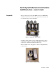
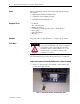
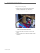
Electrically Held to Mechanical Latch Contactor • Retrofit Instructions 3 2. Using two 7/16” wrenches, loosen the auxiliary contact assemblyretaining bolt and slide the electrically held auxiliary contact assembly out of the front of the contactor. 3. Disconnect the coil leads from the auxiliary contact assembly using a Phillips Screwdriver. Figure 3 – Disconnecting Coil Leads from Auxiliary Contact Assembly Install the Latch Mechanism 1.
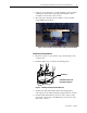
4 Electrically Held to Mechanical Latch Contactor • Retrofit Instructions Figure 5 – Contactor (Front/bottom View) Showing Mounting Bolts for Latch Mechanism ATTENTION The return springs exert a significant force on the armature plate. To avoid injury, do not place fingers between the armature plate and the stop bracket at any time. 5.
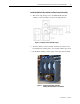
Electrically Held to Mechanical Latch Contactor • Retrofit Instructions 5 Install the Mechanically Latched Auxiliary Contact Assembly 1. Wire the closing and trip coils to the Mechanically Latched auxiliary contact assembly as shown in the diagram below: Figure 6 – Auxiliary Contact Assembly Layout 2. Slide the auxiliary contact assembly back into the contactor and hand tighten the retaining bolt so the assembly remains in position. 3. Re-Install the auxiliary actuator plate on the main shaft assembly.
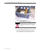
6 Electrically Held to Mechanical Latch Contactor • Retrofit Instructions Auxiliary Contact Assembly Set-Up 1. Clamp the contactor closed from the back of the unit, using a C-Clamp (or clamping fixture, part no. 80154-149-51). 2. Insert a 0.030” (0.76 mm) feeler gauge between the plastic auxiliary contact actuator and the steel actuator plate. (See Figure 8) Figure 8 – Set-up of the Auxiliary Contact Assembly 3. Slide the assembly fully forward, until the contacts have fully engaged. 4.
Electrically Held to Mechanical Latch Contactor • Retrofit Instructions 7 Mechanical Latch Mechanism Set-Up 1. Place the contactor on its side. 2. With the contactor still clamped closed, set the gap between the Latch Roller and the contactor armature plate to 0.01” using a feeler gauge. (See Figure 9) Figure 9 – Mechanical Latch Mechanism Adjustment (as viewed from the front with contactor resting on the left side) 3. Tighten the three mechanism retaining bolts from under the contactor.
8 Electrically Held to Mechanical Latch Contactor • Retrofit Instructions Figure 10 – Contactor (rear view) showing wires to be wire-tied Electrical Test 1. Connect the contactor to the control using the supplied umbilical cord. 2. Test the latch by electrically engaging the contactor using the control circuit. 3. If the contactor fails to latch, re-calibrate the gaps between the auxiliary contacts and contact actuator plate and the gap between the latch roller and contactor armature plate.
Medium Voltage Products, 135 Dundas Street, Cambridge, ON, N1R 5X1 Canada, Tel: (1) 519.740.4100, Fax: (1) 519.623.8930, www.ab.com/mvb Publication 1500-IN001B-EN-E – June 2013 Supersedes Publication 1500-IN001A-EN-P – September 2005 Copyright © 2013 Rockwell Automation, Inc. All rights reserved. Printed in Canada.