
Owner's manual


Contactor Product Description 1-3
1502-UM050D-EN-P – June 2013
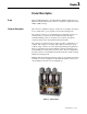
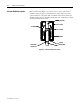
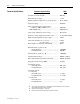
Standard Electrically Held The standard electrically held contactor consists of three vacuum bottles. An
Contactor Operation electro-magnet assembly and a mechanical linkage are used to close the
contacts (Figure 1.3).
• When the control circuit is energized, the current creates an
electromagnet in the closing coil and hold-in coil.
• The electromagnet pulls the armature plate towards the coils’ core,
rotating the shaft and causing the actuator plate to move upwards.
• As the actuator plate moves, it pushes the insulator and movable shaft
up, closing the contacts in the vacuum bottle.
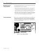
• The control circuit economizing/auxiliary contacts, on the left side of the
contactor, change from the normally closed state to open as the contactor
closes. This de-energizes the closing coil.
• The hold-in coil remains energized and keeps the contactor closed.
• De-energizing the hold-in coil opens the contactor.
Note: The contactor requires external control relays and a rectification
circuit to control the standard DC closing and hold-in coils on the
contactor. (Refer to Chapter 3 for typical control schematics.)
Insulator
Armature Plate & Shaft
Auxiliary Actuator
Armature Stop Bracket
Control Wire Plug
Line Terminal
Vacuum Bottle
Load Terminal
Flexible Bus
Return Spring
Actuator Plate
Gap Adjustment Screw
Magnet/Coil Assembly
C.P.T. Fuse Clip
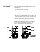
Contactor Open
Contactor Closed
Insulator
Armature Plate & Shaft
Auxiliary Actuator
Armature Stop Bracket
Control Wire Plug
Line Terminal
Vacuum Bottle
Load Terminal
Flexible Bus
Return Spring
Actuator Plate
Gap Adjustment Screw
Magnet/Coil Assembly
C.P.T. Fuse Clip
Insulator
Armature Plate & Shaft
Auxiliary Actuator
Armature Stop Bracket
Control Wire Plug
Line Terminal
Vacuum Bottle
Load Terminal
Flexible Bus
Return Spring
Actuator Plate
Gap Adjustment Screw
Magnet/Coil Assembly
C.P.T. Fuse Clip
Contactor Open
Contactor Closed
Figure 1.3 – Vacuum Contactor Operation