
Owner's manual

1502-UM050D-EN-P – June 2013
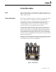
Product Description Chapter 1
Scope .......................................................................................................1-1
Contactor Description ............................................................................ 1-1
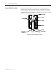
Vacuum Bottle Description .................................................................... 1-2
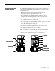
Standard Electrically Held Contactor Operation.................................... 1-3
Mechanically Latched Contactor Operation .......................................... 1-4
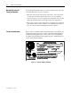
Contactor Identification.......................................................................... 1-4
Contactor Catalog Number Explanation ................................................ 1-5
Contactor Specifications ........................................................................ 1-6
Product Approvals ...................................................................................1-8
Receiving and Handling Chapter 2
Receiving ................................................................................................ 2-1
Handling ................................................................................................. 2-1
Pre-Energization Inspection ................................................................... 2-1
Storage .................................................................................................... 2-2
Vacuum Bottle Integrity Test ................................................................. 2-2
Insulation Resistance Test ...................................................................... 2-5
Installation Chapter 3
Mounting ................................................................................................ 3-1
Electrical Connections ........................................................................... 3-2
Wiring and Schematic Diagrams
Electrically Held Contactor, 120 V AC (Normal Drop-out Time) .... 3-3
Electrically Held Contactor, 230 V AC (Normal Drop-out Time) .....3-4
Electrically Held Contactor, 120 V AC (Fast Drop-out Time) ........3-5
Electrically Held Contactor, 230 V AC (Fast Drop-out Time) ........3-6
Mechanically Latched Contactor, 120 V AC ...................................3-7
Typical Electrical Diagram for 400 amp FVNR Controller
with Electrically Held Contactor, 120 V AC ................................3-8
Typical Electrical Diagram for 400 amp FVNR Controller
with Mechanically Latched Contactor, 120 V AC ........................3-9
Table of Contents