Medium Voltage Contactor (Series D) Bulletin 1502 • 400A 2400 to 7200 volts User Manual
Important User Information Read this document and the documents listed in the Additional Resources section about installation, configuration, and operation of this equipment before you install, configure, operate, or maintain this product. Users are required to familiarize themselves with installation and wiring instructions in addition to requirements of all applicable codes, laws, and standards.
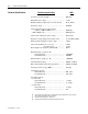
Table of Contents Product Description Chapter 1 Scope .......................................................................................................1-1 Contactor Description ............................................................................ 1-1 Vacuum Bottle Description .................................................................... 1-2 Standard Electrically Held Contactor Operation.................................... 1-3 Mechanically Latched Contactor Operation ...................
ii Table of Contents – 400 A Medium Voltage Contactor User Manual Maintenance Chapter 4 Tool Requirements ................................................................................. 4-1 Recommended Torque Values ............................................................... 4-1 Routine Maintenance.............................................................................. 4-1 Vacuum Bottle Replacement and Set-up Procedure .............................. 4-4 Coil Replacement Procedure ............
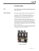
Chapter 1 Product Description Scope This User Manual applies to the Allen-Bradley, Bulletin 1502 (Series D), 400 A electrically held vacuum contactors, designed for applications in the 2400 to 7200 volt range. Contactor Description The contactor is suitable for all types of AC loads, for example: three-phase motors, transformers, power capacitors and resistive heating loads.
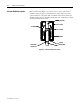
1-2 Contactor Product Description Vacuum Bottle Description Each vacuum bottle (Figure 1.2) consists of two contacts enclosed in a ceramic housing: an upper contact mounted to a fixed shaft, and a lower contact mounted to a movable shaft. A stainless steel bellows ensures the vacuum integrity of the bottle while letting the lower contact move towards and away from the fixed contact. Fixed shaft Ceramic Arc Shield Contacts Bellows Bearing Contact Wear Indicator Line Movable Shaft Figure 1.
Contactor Product Description Standard Electrically Held Contactor Operation 1-3 The standard electrically held contactor consists of three vacuum bottles. An electro-magnet assembly and a mechanical linkage are used to close the contacts (Figure 1.3). • When the control circuit is energized, the current creates an electromagnet in the closing coil and hold-in coil. • The electromagnet pulls the armature plate towards the coils’ core, rotating the shaft and causing the actuator plate to move upwards.
1-4 Contactor Product Description Mechanically Latched Contactor Operation The mechanically latched contactor operates in much the same way as the electrically held with only a few exceptions. • When the control circuit is energized, current flows only to the closing coil and creates an electromagnet (the hold-in coil is not supplied). • Once the contactor is closed, a spring-loaded mechanism moves a roller against the armature plate to hold it against the electromagnetic core.
Contactor Product Description Contactor Catalog Number Explanation 1-5 The following catalog number explanation is used to identify the contactor and should be used when contacting your local Rockwell Automation Sales office, or the factory, for assistance. Table 1.
1-6 Contactor Product Description Contactor Specifications Contactor Ampere Rating Continuous current rating 400 amps Maximum rated voltage ............................................. 7.2 kV Maxium ambient temperature (for rated current) ...... 40°C (104°F) Frequency rating ........................................................ 50/60 Hz Short circuit interruption current rating: – 1500 V to 5000 V (RMS sym.) ........................ – 7200 V (RMS sym.) ........................................
Contactor Product Description Contactor Ampere Rating 1-7 400A Mechanical latch trip coil inrush current • At 120 VAC ........................................................ • At 230 VAC ........................................................ 5.1 amps N/A Coil continuous (economized) current • At 120 VAC ........................................................ • At 230 VAC ........................................................ 0.13 amps 0.11 amps Coil pick-up voltage • At 120 VAC ...............
1-8 Contactor Product Description Contactor Specifications (cont.) Contactor Ampere Rating 400A Contact gap ....................................................... 4.8 mm (0.19 in.) Contact pressure ............................................... 16 kg (35 lb) Weight ............................................................. 21.8 kg (48 lb) Auxiliary contacts: – electrically held ................................... 2 N.O., 2 N.C. – mechanical latch .................................. 3 N.O., 2 N.C.
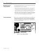
Chapter 2 Receiving and Handling Receiving The contactors have been tested both mechanically and electrically before leaving the factory. Immediately upon receiving the contactor, remove the packing material and check the contactor for possible shipping damage. If damage is found, do not discard any of the packaging material and, if possible, note the damage on the “Bill of Lading” before accepting the shipment. Report any damage immediately to the claims office of the common carrier.
2-2 Receiving and Handling Storage If it is necessary to store the contactor before it is put into service, be certain to store it in a clean, dry, dust- and condensation-free area. Do not store contactor outdoors. Storage temperature should be maintained between -20°C to 65°C (-4°F to 149°F). If storage temperature fluctuates or if humidity exceeds 85%, space heaters should be used to prevent condensation.
Receiving and Handling 2-3 High-potential test instruments can be purchased to perform the vacuum bottle integrity test. A Megger cannot be used to measure vacuum integrity because the voltage is too low. One of the following AC Hi-pot testers is recommended as a test instrument. MANUFACTURER ADDRESS Mitsubishi Type VI #4U17 Jennings Model JHP-70A Hipotronics Model 7BT 60A Chicago, Ill., USA San Jose, CA., USA Brewster, NY, USA 1.
2-4 Receiving and Handling Vacuum Bottle Integrity Test (cont.) Vacuum Checker Vacuum Contactor in open position Figure 2.1 – Vacuum Bottle Integrity Test Circuit Table 2.A – Vacuum Integrity Testing Values Test Vacuum Integrity Dielectric Test Voltage (AC) System Duration 16.0 kV 60 s Allowable Leakage < 5 mA The vacuum integrity cannot be tested using a Megger, as the voltage of a Megger is too low. The allowable leakage current value shown in Table 2.
Receiving and Handling 2-5 DC Hi-pot testing is unreliable because of a phenomenon known as Cathode Ray Tube Effect. This occurs when one contact of the vacuum bottle has a deformity, such as a burr or deposit, while the other contact remains flat and true. This sets up leakage currents which flow from a small surface to a large surface in one direction and vice versa when the polarity of the tester is changed.
2-6 Receiving and Handling 1502-UM050D-EN-P – June 2013
Chapter 3 Installation Mounting The electrically held and the mechanically latched contactors are fixed mounted (bolted down) in the controller’s cabinet. Two retaining tabs at the rear of the contactor’s molded base can be used for mounting. The two mounting slots at the front of the contactor’s molded base are used to secure the contactor with 1/4-in. bolts. The appropriate mounting configuration is provided inside the power cells of Allen-Bradley controllers.
3-2 Installation Electrical Connections A wire harness connects the control wiring to the contactor from the low voltage control panel. The harness connects to a wire plug on the lower left side of the contactor. If the contactor is supplied as an OEM component for installation in a custom application, an optional control panel with connecting wire harness is available from Rockwell Automation.
Installation Wiring and Schematic Diagrams Figure 3.
3-4 Installation Wiring and Schematic Diagrams (cont.) Figure 3.
Installation Figure 3.
3-6 Installation Wiring and Schematic Diagrams (cont.) Figure 3.
Installation Figure 3.
3-8 Installation Figure 3.
O/L Installation Figure 3.
3-10 Installation 1502-UM050$-EN-P – *UNE
Chapter 4 Maintenance Tool Requirements Important: Some components of this product incorporate Imperial hardware. Rockwell Automation recommends the use of the appropriate tools to successfully complete the maintenance procedures on these components. If you cannot obtain such tools, contact your area Rockwell Automation sales office for assistance. When maintenance is performed on the vacuum contactor, the following tools may be required: • • • • • • • • • • • • Recommended Torque Values 3/8-in.
4-2 Maintenance Routine Maintenance (cont.) ATTENTION To avoid shock hazards, lock out incoming power and disconnect the control plug from the contactor before working on the unit. Verify with a hot stick or meter that all circuits are voltage free. Failure to do so may result in severe burns, injury or death. The following should be carried out on an annual basis or whenever a contactor is serviced: 1.
Maintenance 4-3 3. HiPot test (Refer to Page 2-2) • Check the vacuum bottle integrity. • Check the insulation resistance. 4. Lubrication • Using Aeroshell No. 7 (1 oz. tube, Part No. 40025-198-01) grease the actuator plate where the overtravel springs and washers make contact (Figure 4.2). Insulator Grease Grease Actuator Plates Figure 4.2 – Grease Locations • Using Aeroshell No. 7 (1 oz. tube, Part No.
4-4 Maintenance Vacuum Bottle Replacement and Set-Up Procedure Under normal conditions, vacuum bottles will last up to 1,000,000 operations; however, all three bottles must be replaced if any wear indicator line reaches the bearing (regardless of the number of operations). Use the following procedure to remove and replace the vacuum bottles. This procedure can be performed with the contactor remaining in the power cell of the controller.
Maintenance 4-5 Insulator Stud Load Terminal Nut Figure 4.5 – Removal of Vacuum Bottles 5. Install a new bottle by tilting an insulator forward and threading the bottle onto the stud (reverse of Step 3). Take care to ensure the threads are aligned as cross-threading can occur. Thread the bottle down, leaving a gap of approximately 4.82 mm ± 0.25 mm (0.190 in. ± 0.01 in.) between the top of the bottle and the bottom surface of the line terminal, as shown in Figure 4.6.
4-6 Maintenance Vacuum Bottle Replacement and Set-up Procedure (cont.) 7. Close the contactor by using the TEST control circuit in the starter. Insert a feeler gauge of 0.065 in. (1.65 mm) into the overtravel gap of a bottle assembly (Figure 4.7). Rotate the insulator until the gap is correctly set. Repeat this step for the two remaining bottles. This step must be performed accurately because it establishes synchronization between the three vacuum bottles. Overtravel Gap 0.065 in. [1.65 mm] Figure 4.
Maintenance 4-7 9. The contact gaps must be synchronized within 0.02 in. (0.5 mm). If the gaps are not synchronized, rotate the insulators as required to achieve this. Make sure the overtravel remains a minimum of 0.065 in. (1.65 mm) on each bottle. 10. Tighten the load terminal nut on each bottle assembly. To do this without damaging the bellows, apply wrenches to the load terminal nut and to the flattened section of the movable bottle shaft.
4-8 Maintenance Coil Replacement Procedure ATTENTION To avoid shock hazards, lock out incoming power and disconnect the control plug from the contactor before working on the unit. Verify with a hot stick or meter that all circuits are voltage free. Failure to do so may result in severe burns, injury or death. Refer to Chapter 6 for the part number(s) required for this procedure. 1. Remove the auxiliary actuator, front stop bracket and armature plate as shown in Figure 4.10.
Maintenance 4-9 Closing Coil Hold-in Coil Retaining Ring Auxiliary Assembly Retaining Bolt Auxiliary Assembly Figure 4.11 – Coil Removal 4. Disconnect the coil leads (take note of their location). Connect the leads of the new coil, making sure that all metal-oxide varistors (MOVs) and/or diodes are secure. Refer to the appropriate wiring diagram in this manual if further control wiring details are required. 5. Slide the new coil into position and install the retaining ring on the core.
4-10 Maintenance Auxiliary Contact Set-up Procedure Important: This procedure applies to adjustment of existing auxiliaries and installation of new auxiliaries. Under normal conditions, auxiliaries will last at least 1,000,000 operations. If auxiliary contacts must be replaced, discard the entire assembly and install a new assembly. This is easier than replacing a single contact block. Refer to Chapter 6 for the part number(s) required for this procedure.
Maintenance 4-11 1. Loosen the nuts on the auxiliary assembly retaining bolt. This will require loosening and removal of the first nut which secures a ground wire at this location. Leave one nut loosened just enough to permit the assembly to slide along the adjustment slot as shown in Figure 4.13. . Auxiliary Assembly Retaining Bolt Figure 4.13 – Auxiliary Contact Adjustment 2. Slide the clamping fixture (part number 80154-149-51) over the top of the armature stop bracket, Figure 4.14.
4-12 Maintenance Auxiliary Contact Set-up Procedure (cont.) Figure 4.15 – Closing the Contactor with the aid of a wrench 4. After the top screw is finger tight, continue to tighten this screw with a hand tool. Note: The armature stop bracket will flex a little; this is acceptable but do not over-tighten and bend the armature stop plate. It is important that the armature plate is held tightly against the magnet cores. The contactor must be fully closed. 5. Place a wide blade 0.030 in. (0.
Maintenance 4-13 Put feeler gauge here Auxiliary Actuator Bolt 0.030 in. [0.76 mm] Figure 4.17 – Gauging Auxiliary Contact Location 6. With the gauge in place, slide the assembly forward until the contact actuator bottoms out. With the gauge still in place, carefully tighten the auxiliary assembly retaining nut. Important: Always use a wrench to hold the bolt head as you tighten the nut. Make sure the auxiliary assembly does not move as you tighten the nut. 7.
4-14 Maintenance Mechanical Latch Trip Coil Replacement Procedure The following procedure requires the removal of the contactor from the cabinet (open contactor first). • Remove the two mounting bolts at the front of the contactor. • Disconnect the incoming and load line connections at the rear of the contactor. • Disconnect the interlock rod from the operating lever on the right side of the contactor. • Remove the contactor from the cabinet. 1.
Maintenance 4-15 2. Remove the armature plate and front stop as shown in Figure 4.19. Armature Plate Stop Bracket Figure 4.19 – Access to Mechanical Latch 3. Disconnect the trip coil leads from the auxiliary assembly. Take note of the lead termination points. 4. Pull the latch assembly forward and out of the contactor as shown in Figure 4.20. The loose mounting bolts can be re-installed later.
4-16 Maintenance Mechanical Latch Trip Coil Replacement Procedure (cont.) Mechanical Latch Mechanism Assembly Figure 4.20 – Access to Replace Coil 5. Remove the roller shaft retaining ring on the right-hand side, and slide the roller shaft out to the left. Remove the trip core mounting screw as shown in Figure 4.21 and remove the coil and core (earlier version contactors with four latch mounting bolts do not have a trip core mounting screw).
Maintenance 4-17 8. Route the trip coil leads as shown in Figure 4.22 and reconnect them to the auxiliary terminals. Secure the leads to the back panel of the housing with wire ties. Refer to the appropriate wiring diagram in this manual if control wiring details are required. Access to Trip Coil Lead Terminals Trip Coil Leads Figure 4.22 – Trip Coil Lead Routing 9. Replace the armature plate and the front stop. Position the front stop by resting it lightly against the armature plate. 10.
4-18 Maintenance Mechanically Latched Contactor 1. The overtravel, contact gap and auxiliary set-up procedures are the same Set-Up Procedure for mechanically latched contactors as they are for electrically held contactors except that instead of energizing the contactor with the “TEST” circuit, the contactor must be held closed mechanically by means of a clamp or special fixture as shown in Figure 4.23.
Maintenance 4-19 Insert feeler gauge here. 0.010 in. [0.25 mm] Figure 4.24 – Gauging Mechanical Latch Location 4. With the contactor still clamped, depress the latch lever and release allowing it to spring up. Ensure smooth, unimpeded motion. 5. Remove the clamp and allow the armature to move out against the roller such that the contactor is in the “latched” condition. ATTENTION The return springs exert a significant force on the armature plate.
4-20 Maintenance Altitude Adjustment Altitude will affect the performance of a vacuum contactor. Atmospheric pressure assists in closing the main contacts by exerting force on the bellows at the movable end of the vacuum bottles. The force is proportional to the difference between the internal bottle pressure and external atmospheric pressure and adjustments to the operating mechanism must be made to balance the change in closing force.
Chapter 5 Troubleshooting If an operating problem occurs, use the following troubleshooting chart to isolate the cause of the failure and find corrective action. If the corrective action fails to resolve the problem, consult your local Rockwell Automation field support representative. Table 5.
5-2 Troubleshooting 1502-UM050D-EN-P – June 2013
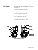
Chapter 6 Spare Parts 1 2 (Elect. Held) 3 (Mech. Latch) 6 10 11 (Elect. Held) 12 (Mech. Latch) 6 9 7 4 Figure 6.1 – Bulletin 1502 • 400 A Electrically Held Vacuum Contactor 16 15 5 13 14 Figure 6.
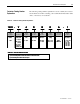
Spare Parts 6-2 Table 6.A – Spare Parts Description of Parts 120 V Control Item Part Number 400 A 1 Three (3) Vacuum Bottles X 80157 2 Closing Coil (electrically held) 80153-576-51 3 Closing Coil (mechanical latch) 80154-134-51 4 Hol 5 d-in Coil 80153-575-51 Mechanical Latch Trip Coil (120 VAC) Auxiliary Assemblies 6 80153-554-52 Elect.
Medium Voltage Products, 135 Dundas Street, Cambridge, ON, N1R 5X1 Canada, Tel: (1) 519.740.4100, Fax: (1) 519.623.8930, www.ab.com/mvb Publication 1502-UM050D-EN-P – June 2013 Supersedes Publication 1502-UM050C – December 2004 Copyright © 2013 Rockwell Automation. All rights reserved. Printed in Canada.