
User Manual


1500-IN059C-EN-E – June 2013
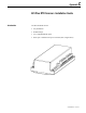
C-2 825 Plus RTD Scanner • Installation Guide
Failuretofollowthesestepscanresultindamagetothe
equipmentand/orpersonalinjury.
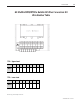
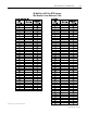
1. EnsuretheRTDwiresaredisconnectedfromtheGEMultilinMPM/MTM
module.UsingthewirenumbertableinAppendixC,markeachwirewith
thecorrespondingGEMultilinrelayterminalblocknumber.
2. Mountthe825PlusRTDScannerinanappropriatelocationwithinthelow
voltagecompartment.The825PlusRTDscannermaybemountedremote
fromthecontroller,i.e.nearthemotor.
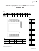
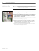
3. Routeandconnectthesuppliedbreopticcablebetweenthe825PlusRTD
scannerandthe825Plusrelay.(Figure C.1)
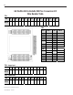
4. RerouteandconnecttheRTDwirestothecorresponding825PlusRTD
Scannerterminalblocks.Usethewirenumbertablecreatedinstep1to
verifythewirenumbersandtheterminalblocklocation.
5. RefertotheelectricaldiagramsandtheRTDwirenumbercross-reference
tableprovidedtoensureproperconnections.
Installation Instructions
Figure C.1
A T T E N T I O NA T T E N T I O N