
User Manual


1500-IN059C-EN-E – June 2013
4-4 Installation
Preparing Low Voltage Door
for 825 Plus
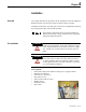
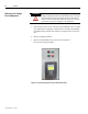
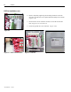
1. Once the door has been removed, place the door on a level work
surface.
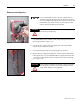
2. Position an 825 Plus Mounting Collar squarely on the low voltage
door to align with the existing GE Multilin relay mounting notes.
(Figure 4.5)
3. Using the collar as a template, lightly trace the cutout area on the
inside and outside of the collar.
This outline represents the minimum
and maximum size required by the 825 Plus relay. (Figure 4.6)
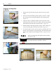
4. Double-check the measurements before cutting. W
ith a cutting tool,
cut on the outside edge of the inside cutout trace. (Figure 4.7)
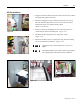
5. To ensure the hole is of the correct size, place a mounting collar over
th
e hole. There should be no metal showing on the inside of the collar,
and the collar should not pass through the cutout. (Figures 4.8 and
4.9)
Remove all metal-chips and splinters before mounting
the 825 Plus relay.
Failure to remove all metal chips and splinters can result
in equipment damage or hazardous operation.
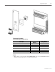
Figure 4.5
Figure 4.6
Figure 4.7
Figure 4.8
Figure 4.9
ATTENTION
IMPORTAN T