Modular Protection System Conversion Kit INSTALLATION MANUAL GE Multilin to Bulletin 825 Plus
Important User Information Read this document and the documents listed in the Additional Resources section about installation, configuration, and operation of this equipment before you install, configure, operate, or maintain this product. Users are required to familiarize themselves with installation and wiring instructions in addition to requirements of all applicable codes, laws, and standards.
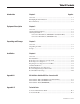
Table Of Contents Introduction Chapter 1 Page No. Overview .................................................................................................... 1-1 Kit Highlights and Limitations ................................................................... 1-2 Personnel Safety ......................................................................................... 1-2 Equipment Description Chapter 2 Overview .......................................................................................
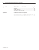
ii Table of Contents – Modular Protection System Conversion Kit • Installation Manual Appendix C 825 Plus RTD Scanner • Installation Guide Page No. Introduction ............................................................................................... C-1 Installation Instructions ............................................................................. C-2 Wire Number Cross-Reference Table ....................................................... C-3 Appendix D Bul.
Chapter 1 Introduction Overview This manual describes the installation of the Bulletin 825 Plus Conversion Kit within a typical medium voltage (MV) controller. Simple troubleshooting is also included. Although this manual outlines the implementation within a medium voltage controller, the basic philosophy also applies for installation within a low voltage controller. To use this manual effectively, you must be familiar with electrical procedures and terminology.
1-2 Introduction Overview (cont.) Kit Highlights and Limitations ATTENTION The elimination of a disturbance may cause the motor to start running again by itself. This may endanger persons or damage equipment. The user must take the necessary safety measures to protect against this type of occurrence so that any danger is avoided. The GE Multilin to Bulletin 825 Plus Conversion Kit provides equivalent features and functionality of the GE Multilin 169/269/269 Plus and 369.
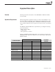
Chapter 2 Equipment Description Overview This chapter describes the features of the GE Multilin to Bulletin 825 Plus Conversion Kit. Operational Requirements Monitoring application parameters and process data of an installation is very important. Even a slight change in the starting and operating behavior of the motor can indicate an impeding fault. The Bulletin 825 Plus helps eliminate the potential trouble before major repairs are necessary and loss of production occurs.
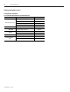
2-2 Equipment Description Operational Requirements (cont.) Function Description Jam Protection Undervoltage Protection GE Multilin 169/269/269 Plus 369 Bul. 825 Plus Parameters Yes Yes Yes Yes (w/metering option) Yes (w/metering option) Yes Ground Fault Alarm Current 1 – 10 A 0.25 – 25 A 0.01 – 25 A Ground Fault Trip Current 1 – 10 A 0.25 – 25 A 0.01 – 25 A Ground Fault Trip Delay Time 1 – 255 s 0 – 255 s 0 s –5s Yes Yes Yes Short Circuit Protection Jam Circuit Current 1.
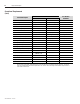
Equipment Description 2-3 Ordering Information Conversion Kit Numbers For GE Multilin 169/269/269 Plus to Bulletin 825 Plus Electrical Drawing Numbers Catalog Number Standard Conversion Kit 80113-650-93 825PK2–BDXXXC Standard Kit with DeviceNet 80113-650-94 825PK2–BDXDXC Standard Kit with Modbus 80113-650-95 825PK2– BDXMXC Standard Kit with RTDs 80113-650-96 825PK2– BDXXPC Standard Kit with RTDs and DeviceNet 80113-650-97 825PK2– BDXDPC Standard Kit with RTDs and Modbus 80113-650-98 82
2-4 Equipment Description Ordering Information (cont.
Equipment Description 2-5 Conversion Kit Numbers For GE Multilin 369 to Bulletin 825 Plus Electrical Drawing Numbers Catalog Number Standard Conversion Kit 80113-650-87 825PK3–BDVXXC Standard Kit with DeviceNet 80113-650-88 825PK3– BDVDXC Standard Kit with Modbus 80113-650-89 825PK3– BDVMXC Standard Kit with RTDs 80113-650-90 825PK3– BDVXPC Standard Kit with RTDs and DeviceNet 80113-650-91 825PK3– BDVDPC Standard Kit with RTDs and Modbus 80113-650-92 825PK3– BDVMPC Description NOTE: •
2-6 Equipment Description Ordering Information (cont.
Chapter 3 Unpacking and Storage Overview This chapter describes the procedures for unpacking, inspecting, and storing the GE Multilin to Bulletin 825 Plus Conversion Kit. Unpacking Your Kit As you unpack the conversion kit, follow the steps listed below: 1. Handle each component carefully to avoid damage. 2. Unpack the box(es) enough to inspect the shipment for missing or damaged equipment. 3.
3-2 Unpacking and Storage 1500-IN059C-EN-E – June 2013
Chapter 4 Installation Overview This chapter describes the procedures for the installation of the GE Multilin to Bulletin 825 Plus Conversion Kit within a medium voltage controller. Installation within other controller types can also be accomplished by following the principal philosophy of the retrofit described. Pre-Installation IMPORTANT This manual is intended for use by personnel trained and familiar with medium voltage, solid-state power equipment, and general industrial controls.
4- Installation Removing Low Voltage Door Components ATTENTION Disconnect and lockout all sources of power entering the low voltage compartment where the GE Multilin relay is located. This may include opening the main disconnect of isolation switch. Failure to disconnect and lock out power can result in personal injury and/or damage to the equipment. 1. Disconnect the control wires connected to the GE Multilin relay.
Installation 4- Removing Low Voltage Door Figure 4.3 IMPORTANT It is recommended to remove the low voltage doors to facilitate cutting the mounting hole for 825 Plus. The hole can be cut without removing the door if proper tools are used and blankets, drop sheets or tarps are used to prevent drill and saw chips from entering the controller. ATTENTION Failure to check for clearance can result in damage to equipment and/or personal injury. 1. Remove all door-mounted devices.
4- Installation Preparing Low Voltage Door for 825 Plus 1. Once the door has been removed, place the door on a level work surface. 2. Position an 825 Plus Mounting Collar squarely on the low voltage door to align with the existing GE Multilin relay mounting notes. (Figure 4.5) Figure 4.5 3. Using the collar as a template, lightly trace the cutout area on the inside and outside of the collar. This outline represents the minimum and maximum size required by the 825 Plus relay. (Figure 4.6) 4.
Installation 4- 825 Plus Installation 1. Align the 825 Plus interface panel at the rear of the LV door with the existing mounting holes and cutout. 2. With the self tapping screws provided, mount the front cover and fasten the interface panel to the rear of LV door, which is located between the cutout cover and the interface panel. (Figures 4.10 and 4.11) Figure 4.10 3. Ensure an extra long self-tapping screw is used in the top left, as viewed from the front of mounting hole. (Figure 4.11) 4.
4- Installation 825 Plus Installation (cont.) 6. Before completely tightening the mounting hardware ensure the 825 Plus is mounted on a level plane both horizontally and vertically. (Figure 4.18) 7. Reconnect the various interface connectors on the back of the 825 Plus. (Figures 4.14, 4.16 and 4.17) 8. Ensure all ground wires are connected. (Figure 4.20) Figure 4.15 Figure 4.16 – Cable to Converter Module 1500-IN059C-EN-E – June 2013 Figure 4.17 – Rear View Figure 4.
Installation 4- Re-Installing the Low Voltage Door 1. Reinstall the low voltage door. Caution must be taken when re-installing the door. It is recommended that two people remount the door – one person to hold the door and a second person to replace the hinge pins. (Figure 4.19) ATTENTION Ensure sufficient personnel are present to safely replace the low voltage door. Failure to do so may result in personal injury and/or damage to the equipment. 2. Remount all door-mounted devices that were removed.
4- Installation Reconnecting Existing Control Circuit 1. Using the provided spiral wrap, combine the existing and new door control wire bundle. (Figure 4.21) 2. Re-route the existing control wiring to the existing door components and through the 825 Plus interface panel. Care must be taken to ensure enough space to allow door closure. (Figures 4.21 and 4.22) 3. Secure the existing wiring to the door with provided sticky pads and tie wraps.
Installation 4- If the RTD option is used, wire the RTDs to the 825 Plus RTD Scanner voltage panel. Refer to the RTD Interface Installation Guide (Appendix C) for additional information on RTD wiring. ATTENTION Failure to reconnect all wires and cables correctly may result in equipment damage, personal injury and/or death. 5.
4-10 Installation Post Installation (Testing) ATTENTION Failure to follow these steps can result in damage to equipment and/or personal injury. 1. Inspect the interior of the enclosure for contamination, loose bolts, tools or metal chips, and vacuuming the enclosure is recommended. 2. Account for all the tools used. If a tool or hardware is unaccounted for, do not energize the equipment. 3. Inspect the wiring and the control scheme to ensure proper operation.
Installation 4-11 8. Test the control circuit functionality by electrically operating the contactor (air or vacuum) in test mode. This may require the use of test jumpers depending on the control circuit. Refer to original drawings supplied with the equipment. (Figure 4.31) 9. Program the 825 Plus with the correct motor and protection parameters. (Figure 4.32) Refer to Publication 825-UM004B-EN-P, included with the 825 Plus, for programming instructions. 10. Turn test switch to OFF.
4-12 Installation 1500-IN059C-EN-E – June 2013
Appendix A GE Multilin 169/269/269 Plus to Bulletin 825 Plus Conversion Kit Wire Number Table TB1 TB# 29 30 31 32 33 34 35 36 37 38 39 40 41 42 43 Wire # TB2 TB# Wire # 44 45 84 85 – – – – – – – – 52 53 54 55 56 57 58 TB3 TB# 83 82 81 80 Wire # 79 78 77 76 75 74 73 72 59 – – – – – – – – Photocopy for multiple unit use.
A-2 GE Multilin 369 to Bulletin 825 Plus Conversion Kit Wire Number Table TB1 TB# 111 112 113 114 115 116 117 118 119 120 121 122 123 124 125 126 Wire # TB2 TB3 – Upper Level TB# 90 91 92 93 94 94 105 – 96 97 98 99 100 Wire # TB3 – Lower Level TB# 101 102 103 104 Wire # Photocopy for multiple unit use.
Technical Data A-3 GE Multilin MPM/MTM to Bulletin 825 Plus Conversion Kit Wire Number Table TB1 – Upper Level TB# 9 10 11 12 13 14 15 16 3 4 5 6 7 8 17 Wire # TB1 – Lower Level TB# 1 2 Wire # Photocopy for multiple unit use.
A-4 1500-IN059C-EN-E – June 2013
Appendix B Technical Data 825 Plus Refer to Publication 825-UM004_-EN-P. Conversion Kit Interface Panel Description Specification Terminals (TB1) Type 1492Approvals Voltage Rating Maximum Current Wire Range Wire Strip Length Recommended Tightening Torque Insulation Temperature Range CA3 CSA certified and UL listed 600 V AC/DC 20 A 0.5 to 1.5 mm2 (#22 – #14 AWG) Prepared conductors only 12 lb.-in. (1.
B-2 Technical Data 1500-IN059C-EN-E – June 2013
Appendix C 825 Plus RTD Scanner • Installation Guide Introduction The 825 Plus RTD scanner: • • • • easy installation modular design (12) configurable RTD inputs Fiber-optic communication port to 825 Plus (max.
C- 825 Plus RTD Scanner • Installation Guide Installation Instructions ATTENTION Failure to follow these steps can result in damage to the equipment and/or personal injury. 1. Ensure the RTD wires are disconnected from the GE Multilin MPM/MTM module. Using the wire number table in Appendix C, mark each wire with the corresponding GE Multilin relay terminal block number. 2. Mount the 825 Plus RTD Scanner in an appropriate location within the low voltage compartment.
825 Plus RTD Scanner • Installation Guide C- GE Multilin to 825 Plus RTD Scanner Wire Number Cross-Reference Table Photocopy for multiple unit use.
C- 825 Plus RTD Scanner • Installation Guide 1500-IN059C-EN-E – June 2013
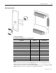
Appendix D Bulletin 825 Plus Kit Component Configuration (GE 169 / 269 / 269 Plus) Communication Card - DeviceNet - Modbus 825 Plus 825-MCM Current Converter Module (Standard Kits with no metering) 825 Plus Interface Panel 825 Plus RTD Scanner GE MTM/MPM to 825 Plus Interface Panel (Standard Kits with metering) 1500-IN059C-EN-E – June 2013
D-2 Bul.
Installation 4-11 8. Test the control circuit functionality by electrically operating the contactor (air or vacuum) in test mode. This may require the use of test jumpers depending on the control circuit. Refer to original drawings supplied with the equipment. (Figure 4.31) 9. Program the 825 Plus with the correct motor and protection parameters. (Figure 4.32) Refer to Publication 825-UM004B-EN-P, included with the 825 Plus, for programming instructions. 10. Turn test switch to OFF.
4-12 Installation 1500-IN059C-EN-E – June 2013
Appendix A GE Multilin 169/269/269 Plus to Bulletin 825 Plus Conversion Kit Wire Number Table TB1 TB# 29 30 31 32 33 34 35 36 37 38 39 40 41 42 43 Wire # TB2 TB# Wire # 44 45 84 85 – – – – – – – – 52 53 54 55 56 57 58 TB3 TB# 83 82 81 80 Wire # 79 78 77 76 75 74 73 72 59 – – – – – – – – Photocopy for multiple unit use.
A-2 GE Multilin 369 to Bulletin 825 Plus Conversion Kit Wire Number Table TB1 TB# 111 112 113 114 115 116 117 118 119 120 121 122 123 124 125 126 Wire # TB2 TB3 – Upper Level TB# 90 91 92 93 94 94 105 – 96 97 98 99 100 Wire # TB3 – Lower Level TB# 101 102 103 104 Wire # Photocopy for multiple unit use.
Technical Data GE Multilin MPM/MTM to Bulletin 825 Plus Conversion Kit Wire Number Table TB1 – Upper Level TB# 9 10 11 12 13 14 15 16 3 4 5 6 7 8 17 Wire # TB1 – Lower Level TB# 1 2 Wire # Photocopy for multiple unit use.
A-4 1500-IN059C-EN-E – June 2013
Appendix B Technical Data 825 Plus Refer to Publication 825-UM004_-EN-P. Conversion Kit Interface Panel Description Specification Terminals (TB1) Type 1492Approvals Voltage Rating Maximum Current Wire Range Wire Strip Length Recommended Tightening Torque Insulation Temperature Range CA3 CSA certified and UL listed 600 V AC/DC 20 A 0.5 to 1.5 mm2 (#22 – #14 AWG) Prepared conductors only 12 lb.-in. (1.
B-2 Technical Data 1500-IN059C-EN-E – June 2013
Appendix C 825 Plus RTD Scanner • Installation Guide Introduction The 825 Plus RTD scanner: • • • • easy installation modular design (12) configurable RTD inputs Fiber-optic communication port to 825 Plus (max.
C- 825 Plus RTD Scanner • Installation Guide Installation Instructions ATTENTION Failure to follow these steps can result in damage to the equipment and/or personal injury. 1. Ensure the RTD wires are disconnected from the GE Multilin MPM/MTM module. Using the wire number table in Appendix C, mark each wire with the corresponding GE Multilin relay terminal block number. 2. Mount the 825 Plus RTD Scanner in an appropriate location within the low voltage compartment.
825 Plus RTD Scanner • Installation Guide C- GE Multilin to 825 Plus RTD Scanner Wire Number Cross-Reference Table Photocopy for multiple unit use.
C- 825 Plus RTD Scanner • Installation Guide 1500-IN059C-EN-E – June 2013
Appendix D Bulletin 825 Plus Kit Component Configuration (GE 169 / 269 / 269 Plus) Communication Card - DeviceNet - Modbus 825 Plus 825-MCM Current Converter Module (Standard Kits with no metering) 825 Plus Interface Panel 825 Plus RTD Scanner GE MTM/MPM to 825 Plus Interface Panel (Standard Kits with metering) 1500-IN059C-EN-E – June 2013
D-2 Bul.
Medium Voltage Products, 135 Dundas Street, Cambridge, ON, N1R 5X1 Canada, Tel: (1) 519.740.4100, Fax: (1) 519.623.8930, www.ab.com/mvb Publication 1500-IN059C-EN-E – June 2013 Supersedes Publication 1500-IN059B-EN-P – November 2006 Copyright © 2013 Rockwell Automation, Inc. All rights reserved. Printed in Canada.