Modular Protection System Conversion Kit INSTALLATION MANUAL Bulletin 1406 to Bulletin 825 Plus
Important User Information Read this document and the documents listed in the Additional Resources section about installation, configuration, and operation of this equipment before you install, configure, operate, or maintain this product. Users are required to familiarize themselves with installation and wiring instructions in addition to requirements of all applicable codes, laws, and standards.
Table of Contents Introduction Chapter 1 Overview .............................................................................................. 1-1 Kit Highlights and Limitations ............................................................ 1-2 Personnel Safety ................................................................................... 1-2 Equipment Description Chapter 2 Overview ..............................................................................................
ii Table of Contents – Bulletin 1406 to 825 Plus Conversion Kit Installation Manual Appendix C Bulletin 1406-R16 to Bulletin 825P Smart Motor Manager Conversion Kit Introduction.............................................................................................. C-1 Installation Instructions ........................................................................... C-2 Bulletin 825 Plus RTD Scanner Interface Conversion Kit Wire Number Table ......................................................
Chapter 1 Introduction Overview This manual describes the installation of the Bulletin 825 Plus Conversion Kit within a typical medium voltage (MV) controller. Simple troubleshooting is also included. Although this manual outlines the implementation within a medium voltage controller, the basic philosophy also applies for installation within any voltage controller where a Bulletin 1406 has been used. To use this manual effectively, you must be familiar with electrical procedures and terminology.
1-2 Introduction Overview (cont.) Kit Highlights and Limitations ATTENTION The elimination of a disturbance may cause the motor to start running again by itself. This may endanger persons or damage equipment. The user must take the necessary safety measures to protect against this type of occurrence so that any danger is avoided. The Bulletin 1406 to Bulletin 825 Plus Conversion Kit provides most of the features and functionality of the Bulletin 1406.
Chapter 2 Equipment Description Overview This chapter describes the features of the Bulletin 1406 to Bulletin 825 Plus Conversion Kit. Operational Requirements Monitoring application parameters and process data of an installation is very important. Even a slight change in the starting and operating behavior of the motor can indicate an impending fault. The Bulletin 825 Plus helps eliminate the potential trouble before major repairs are necessary and loss of production occurs.
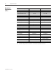
2-2 Equipment Description Operational Requirements (cont.) Function Description Bul. 1406 Parameters Bul. 825 Plus Parameters Yes Yes Jam Protection Undervoltage Protection Yes n Ye Ground Fault Alarm Current 1A – 25A 0.01 – 25A Ground Fault Trip Current 1A – 25A 0.
Equipment Description 2-3 Ordering Information Conversion Kit Numbers Electrical Drawing Numbers Catalog Number Standard Conversion Kit 80113-650-71 825PK1-BDVXXC Standard Kit with DeviceNet 80113-650-72 825PK1-BDVDXC Standard Kit with Modbus 80113-650-73 825PK1-BDVMXC Standard Kit with RTDs 80113-650-74 825PK1-BDVXPC Standard Kit with RTDs and DeviceNet 80113-650-75 825PK1-BDVDPC Standard Kit with RTDs and Modbus 80113-650-76 825PK1-BDVMPC Description NOTE: When ordering a conversio
Equipment Description 2-4 Catalog Number Breakdown Part Standard Conversion Kit Part Description Mounting Bezel (ANSI 49) 80185-279-05 Mounting Bezel (ANSI 61) 80185-279-06 Cutout Cover (ANSI 49) 80185-316-02 Cutout Cover (ANSI 61) 80185-316-03 Base 825 Plus Relay 825-PD 825 Plus I/O Card 825-PIOD 825 Plus Voltage Card 825-PVS 1406 to 825P Interface Panel Assembly 80185-323-52 with DeviceNet 825 Plus DeviceNet Card 825-PDN with Modbus 825 Plus Modbus RTU Card 825-PMB 825 Plus RTD S
Chapter 3 Unpacking and Storage Overview This chapter describes the procedures for unpacking, inspecting, and storing the Bulletin 1406 to Bulletin 825 Plus Conversion Kit. Unpacking Your Kit As you unpack the conversion kit, follow the steps listed below: 1. Handle each component carefully to avoid damage. 2. Unpack the box(es) enough to inspect the shipment for missing or damaged equipment. 3.
3-2 Unpacking and Storage 1500-IN058D-EN-E – June 2013
Chapter 4 Installation Overview This chapter describes the procedures for the installation of the Bulletin 1406 to Bulletin 825 Plus Conversion Kit within a medium voltage controller. Installation within other controller types can also be accomplished by following the principal philosophy of the retrofit described. Pre-installation IMPORTANT This manual is intended for use by personnel trained and familiar with medium voltage, solid-state power equipment, and general industrial controls.
4-2 Installation 825 Plus Interface Panel ATTENTION Disconnect and lockout all sources of power entering the low voltage compartment where the 1406-P16 is located. This may include opening the main disconnect isolation switch. Failure to disconnect and lock out power can result in personal injury and/or damage to the equipment. 1. Disconnect the control wires connected to the 1406-P16.
Installation 4-3 Door Cover 1. Disconnect and remove the communication cable from 1406 programming module, located on the low voltage door. (Figure 4.3) 2. Remove the 1406 programming module from the low voltage door. Save the mounting hardware for use later in the installation process. (Figure 4.4) Figure 4.3 Figure 4.4 3. Use the saved hardware to mount the 1406 door filler cover supplied with the conversion kit. Ensure that the correct colored door filler cover is used.
4-4 Installation Removing Low Voltage Door IMPORT ANT Figure 4.7 It is recommended to remove the low voltage doors to facilitate cutting the mounting hole for 825 Plus. The hole can be cut without removing the door if proper tools are used and blankets, drop sheets or tarps are used to prevent drill and saw chips from entering the controller. If you chose to do so, skip to page 4-5 and ignore page 4-7.
Installation 4-5 Preparing Low Voltage Door for 825 Plus Hinge Side 1. Once the door has been removed, place the door on a level work surface. 2. Position an 825 Plus Mounting Collar squarely on the low voltage door to locate the required cutout. (Figure 4.10) IMPORT ANT Figure 4.10 Position the 825 Plus cutout on the door properly to ensure that the low voltage door and low voltage panel can swing open without difficulty.
4- Installation Preparing Low Voltage Door for 825 Plus (cont.) 1. Mount the 825 Plus through the low voltage door cutout. Remember to place a mounting collar on both sides of the low voltage door. (Figure 4.15) 2. Fasten the 825 Plus to the low voltage door using the mounting hardware provided with the 825 Plus. Tighten the screws with minimal force. Do not over tighten. Figure 4.15 3.
Installation 4-7 Re-installing the Low Voltage Door 1. Re-install the low voltage door. Caution must be taken when reinstalling the door. It is recommended that two people remount the door – one person to hold the door and a second person to replace the hinge pins. (Figure 4.18) ATTENTION Ensure sufficient personnel are present to safely replace the low voltage door. Failure to do so may result in personal injury and/or damage to the equipment. 2. Remount all door-mounted devices that were removed.
4-8 Installation Wiring the Control Circuit 1. Reconnect the control wires to the corresponding 825 Plus Interface Panel terminal blocks. These are located and numbered the same as those on the 1406-P16. Use the wire number table (created as part of the procedures on page 4-2) in Appendix A, to verify the wire numbers and the terminal block location. (Figures 4.20 and 4.21) 2. Using the provided spiral wrap, combine the existing and new door control wire bundles. (Figure 4.22) Figure 4.20 Figure 4.
Installation 4-9 3. Route the new wire harness along the low voltage door to the 825 Plus. (Figure 4.23) 4. Cut, strip, and connect each numbered wire to the corresponding numbered green 825 Plus terminal plug. 5. Route the black converter module cable along the low voltage door and plug the telephone style connector to the back of the 825 Plus. IMPORT ANT Figure 4.23 Refer to the supplied wiring diagram during installation of 825 Plus Interface Panel.
4-10 Installation Post Installation (Testing) ATTENTION Failure to follow these steps can result in damage to equipment and/or personal injury. 1. Inspect the interior of the enclosure for contamination, loose bolts, tools or metal chips, and vacuum clean if necessary. 2. Account for all the tools used. If a tool or hardware is unaccounted for, do not energize the equipment. 3. Inspect the wiring and the control scheme to ensure proper operation.
Installation 4-11 8. Test the control circuit functionality by electrically operating the contactor (air or vacuum) in test mode (Figure 4.26). This may require the use of test jumpers depending on the control circuit. Refer to original drawings supplied with the equipment. 9. Program the 825 Plus with the correct motor and protection parameters (Figure 4.27). Refer to the User Manual publication 825-UM004_-EN-P included with the 825 Plus for programming instructions. 10. Turn test switch to OFF.
4-12 Installation 1500-IN058D-EN-E – June 2013
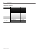
Appendix A Bul. 1406-P16 to Bulletin 825 Plus Conversion Kit Wire Number Table TB1 TB # TB2 Wire # TB # 1 8 2 7 3 6 4 5 5 4 6 3 7 2 8 1 Wire # 9 10 11 12 13 14 15 TB3 16 17 TB # 18 6 19 5 20 4 21 3 22 2 23 1 Wire # (Copy As Required.
A-2 1500-IN058D-EN-E – June 2013
Appendix B Technical Data 825 Plus Refer to Publication 825-UM004_-EN-P. Conversion Kit Interface Panel Description Specification Ground Fault Interposing Current Transformer Primary 1A Secondary 5A Operating Frequency Class 600 Accuracy Primary Impedance Approvals Important: 50/60 Hz V Less than 2% ratio error at 5 VA burden 2.5 ohms CSA certified and UL listed This current transformer is used to step down an existing 50:5 ground fault current transformer.
B-2 Technical Data Conversion Kit Interface Panel (cont.) Description Specification Terminals (TB1 and TB3) Type Approvals Voltage Rating Maximum Current Wire Range Wire Strip Length Recommended Tightening Torque Insulation Temperature Range Screw terminal with wire clamp CSA certified and UL listed 300 V AC/DC 25 A 0.5 to 1.5 mm2 (#22 - #14 AWG) 6.4 mm (0.25 inch) 6-14 lb.-in. (0.7 – 1.
Appendix C Bulletin 1406-R16 to Bulletin 825P Smart Motor Manager Conversion Kit 825 Plus RTD Scanner • Installation Guide Introduction The 825 Plus RTD panel provides: • • • • easy installation modular design (12) configurable RTD inputs Fiber-optic communication port to 825 Plus (max. length 500 m) IMPORTANT The 1406 RTD module provided for eight (8) RTD input, six (6) stator winding RTD inputs, and two (2) bearing RTD inputs.
C-2 RTD Interface Panel • Installation Guide Installation Instructions ATTENTION Failure to follow these steps can result in damage to the equipment and/or personal injury. 1. Ensure the RTD wires are disconnected from the 1406 RTD module. Using the wire number table in Appendix C, mark each wire with the corresponding 1406 RTD module terminal block number. 2. Remove the 1406 RTD module from the low voltage panel. Save all the mounting hardware. 3.
RTD Interface Panel • Installation Guide C-3 Bulletin 825 Plus RTD Scanner Interface Conversion Kit Wire Number Table TB3 TB1 825 Plus RTD Scanner TB # 1406 TB # 1 23 5 — 2 24 4 — 3 26 3 — 1406 TB # Wire # Wire # 825 Plus RTD Scanner TB # 2 — 1 — TB4 TB2 825 Plus RTD Scanner TB # 1406 TB # 1 02 16 32 2 02 15 31 3 03 14 30 4 03 13 32 5 04 12 29 6 05 11 28 7 06 10 27 8 06 9 29 9 07 8 18 10 08 7 18 11 09 6 17 12 09 5 16 13 10 4 15
C-4 RTD Interface Panel • Installation Guide 1500-IN058D-EN-E – June 2013
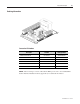
Appendix D Bulletin 825 Plus Component Configuration Communication Card - DeviceNet - Modbus 825 Plus 825 Plus Interface Panel with 825-MCM 825 Plus RTD Scanner Interface Panel 1500-IN058D-EN-E – June 2013
D-2 Bulletin 825 Plus Component Configuration 1500-IN058D-EN-E – June 2013
Appendix E Bulletin 1406 Product Overview 1500-IN058D-EN-E – June 2013
E-2 Bulletin 1406 Product Overview 1500-IN058D-EN-E – June 2013
Medium Voltage Products, 135 Dundas Street, Cambridge, ON, N1R 5X1 Canada, Tel: (1) 519.740.4100, Fax: (1) 519.623.8930, www.ab.com/mvb Publication 1500-IN058D-EN-E – June 2013 Supersedes Publication 1500-IN058C-EN-E – February 2007 Copyright © 2013 Rockwell Automation, Inc. All rights reserved. Printed in Canada.