
Manual

Wiring
3-15
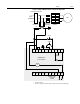
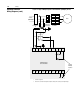
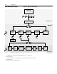
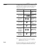
Figure 3.19 Typical Wiring Diagram for Shunt Trip Applications
①
Customer supplied.
②
Refer to the controller nameplate to verify the rating of the control power input voltage.
Stop
➀
Start
➀
➁
3-Phase
Shunt Trip Circuit Breaker
Input Power
Branch
Protection
➀
Fast-acting
SCR Fuses
(optional)
➀
M
➀
➀
➀
➀
L1/1
L2/3
L3/5
T1/2
T2/4
T3/6
➀
11
12 13 14 15 16 17 18 19 20
21
22 23 24 25 26 27 28 29 30
ST
Auxiliary contact
set for Fault
and N.O.
SMC Dialog Plus
Controller
SMC Dialog Plus
Control Terminals