
User Manual


8 SMC™ Flex Quick Start
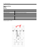
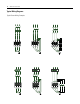
Typical Wiring Diagrams
Typical Power Wiring Examples
L1 L2 L3
T1 T2 T3
Motor
T6
T4
T5
K1
L1 L2 L3
T1 T2 T3
Motor
K1
Diagrams per NEMA Symbology
Delta Connection with
Isolation Contactor
(Optional Mode)
Line Connection with
Isolation Contactor
(Default Mode)
2
1
4
3
6
5
L1 L2 L3
M
3
2
U
K1
2
1
1
4
V
4
3
3
6
W
6
5
5
M
3
L1
2
K1
1
2
1
L2
4
3
4
3
L3
6
2
1
4
3
6
5
5
6
5
U
1
V
1
W
1
W
2
U
2
V
2
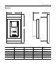
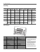
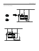
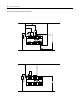
Diagrams per IEC Symbology
L1 L2 L3
T1 T2 T3
Motor
T6
T4 T5
Delta Connection with
Shorted SCR Protection
(Optional Mode)
K1
Delta Connection with
Isolation Contactor
(Optional Mode)
Line Connection with
Isolation Contactor
(Default Mode)
Delta Connection with
Shorted SCR Protection
(Optional Mode)
M
3
L1
2
1
L2
4
3
L3
2
1
4
3
6
5
6
5
U
1
V
1
W
1
W
2
U
2
V
2
2
K1
1
4
3
6
5