Quick Start SMC Dialog Plus™ Controller Bulletin 150
Important User Information Solid-state equipment has operational characteristics differing from those of electromechanical equipment. Safety Guidelines for the Application, Installation and Maintenance of Solid State Controls (publication SGI-1.1 available from your local Rockwell Automation sales office or online at http://www.rockwellautomation.com/literature/) describes some important differences between solid-state equipment and hard-wired electromechanical devices.
Quick Start Introduction This quick start guide provides you with the basic information required to start up your SMC Dialog Plus™ controller. Factory default settings and information regarding installing, programming, and calibrating the controller are described here. The information provided in this Quick Start Guide does not replace the User Manual, which can be ordered or downloaded by visiting www.ab.com/literature.
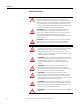
Quick Start General Precautions ATTENTION: Hazardous voltage is present in the motor circuit even when the SMC-Dialog Plus controller is off. To avoid shock hazard, disconnect the main power before working on the controller, motor, and control devices such as Start-Stop push buttons. Procedures that require parts of the equipment to be energized during troubleshooting, testing, etc., must be performed by properly qualified personnel, using appropriate local safety work practices and precautionary measures.
Quick Start Overload ATTENTION: Overload protection in the SMC Dialog Plus controller is disabled from the factory. The user must program the desired overload trip class and motor full load current rating to achieve proper protection ATTENTION: Overload protection should be properly coordinated with the motor. ATTENTION: During slow speed and/or braking operations, current waveforms exhibit non-sinusoidal characteristics.
Quick Start Pump Control ATTENTION: Pump stopping is not intended to be used as an emergency stop. Refer to the applicable standard for emergency stop requirements. ATTENTION: Pump stopping may cause motor heating depending on the mechanical dynamics of the pumping system. Therefore, select the lowest stopping time setting that will satisfactorily stop the pump. Preset Slow Speed ATTENTION: Slow speed running is not intended for continuous operation due to reduced motor cooling.
Quick Start Protective Modules ATTENTION: To protect the Smart Motor Controller (SMC) and/or motor from line voltage surges, protective modules may be placed on the line, load, or both sides of the SMC. Do not place protective modules on the load side of the SMC when when using pump or braking control. ATTENTION: When installing or inspecting the protective module, make sure that the controller has been disconnected from the power source.
Quick Start Wiring Power Wiring Refer to the product nameplate for power lug termination information including: • Lug wire capacity • Tightening torque requirements • Lug kit catalog numbers (97…1000 A) Control Wiring Refer to the product nameplate for control terminal wire capacity and tightening torque requirements. Each control terminal will accept a maximum of two wires. The SMC Dialog Plus controller accepts control power input of either 100…240V AC, (+10/–15%) single-phase, 50/60 Hz or 24V AC/DC.
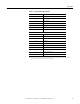
Quick Start Table 2 - Control Terminal Designation 13 Controller Enable Input ➊ 14 Logic Ground 15 Dual Ramp/Option Input ➊ 16 Start Input ➊ 17 Stop Input ➊ 18 Auxiliary Relay Common 19 N.O. Auxiliary Contact #1 20 N.C.
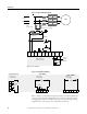
Quick Start Figure 2 - Typical Wiring Diagram L1/1 T1/2 L2/3 T2/4 L3/5 T3/6 3-Phase M❶ Input Power Fast-acting SCR Fuses SMC Dialog Plus (optional) ❶ Controller ❶ Branch Protection ❶ ❶ ❶ Fan Power Terminals (97…1000 A) Stop ❶ Start ❶ 11 12 13 14 15 16 17 18 19 20 Internal Auxiliary Contacts SMC Dialog Plus Control Terminals ❶Customer supplied.
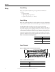
Quick Start Programming The SMC Dialog Plus controller can be programmed with the built-in keypad and LCD display or with the optional Bulletin 1201 human interface modules. Parameters are organized in a four-level menu structure and divided into programming groups. Keypad Description ESC SEL Escape Pressing the Escape key causes the programming system to move up one level in the menu structure.
Quick Start Figure 4 - Menu Structure Hierarchy Power-Up and Status Display ESC or SEL or or or OPERATION LEVEL Choose Mode MODE LEVEL or Control Status Display read only Password Program read/write ➌ ➍ ➊ Search read only ➍ ➌ ESC ➋ Control Logic Fault Queue or Linear List Metering Basic Setup Advanced Setup Faults Calibrate Language ➎ ESC GROUP LEVEL ➋ ➊The SMC Dialog Plus controller does not support EEPROM, Link, Process, or Start-up modes ➋Steps back one level.
Quick Start Figure 5 - Menu Structure Hierarchy, Continued or Linear List Metering Basic Setup Advanced Setup Calibrate Faults Language ➋ GROUP LEVEL ESC ➊ ESC ➊ Volts Phase A-B Volts Phase B-C Volts Phase C-A Current Phase A Current Phase B Current Phase C Wattmeter Kilowatt Hours Elapsed Time Power Factor Mtr. Therm. Usage SMC Option Starting Mode Ramp Time #1 Initial Torque #1 Curr.
Quick Start Factory Default Settings The SMC Dialog Plus controller is pre-programmed with the settings listed in the table below. Parameter Setting Starting Mode Soft Start Ramp Time 10 seconds Initial Torque 70% of locked rotor torque Kickstart Off Energy Saver Off Stall Off Phase Rebalance Off Auxiliary Contacts Normal Service Factor 1.15 Overload Class Off Line Voltage 480 volts Motor FLC 1.0 amps Motor HP Rating 0.
Quick Start Notes: 1. If you plan to use the Bulletin 825 converter module for current feedback to the SMC Dialog Plus controller, this calibration procedure is not necessary. 2. An unbalanced three-phase system may affect the accuracy of the calibration. 3. It is recommended that Parameter #36, Overload Class, is programmed to OFF during the calibration procedure. Calibration requires the motor to be operated at full speed.
Quick Start Description Action 7. You can scroll to the next parameter to view the current measurement in phase A. CURRENT PHASE A ##.# AMPS 8. Scroll to the next parameter to save the Calibrate group settings. 9. Press the Select key. Scroll with the Up/Down keys to Store In EE selection. Press the Enter key to save the settings to EEPROM.
Quick Start Human Interface Modules The Bulletin 1201 human interface modules with control panels can start and stop the SMC Dialog Plus controller. However, the factory default settings disable control commands other than Stop through the serial communication port. To enable motor control from a connected human interface module, you must take the following programming steps: Series A 1. Enter into the Program mode. 2. Select the Linear List programming group. 3.
Quick Start Notes: 18 Rockwell Automation Publication 150-QS002B-EN-P - October 2011
Rockwell Automation Support Rockwell Automation provides technical information on the Web to assist you in using its products. At http://www.rockwellautomation.com/support/, you can find technical manuals, a knowledge base of FAQs, technical and application notes, sample code and links to software service packs, and a MySupport feature that you can customize to make the best use of these tools.